US9772985B2 - Communications control for resource constrained devices - Google Patents
Communications control for resource constrained devices Download PDFInfo
- Publication number
- US9772985B2 US9772985B2 US14/193,443 US201414193443A US9772985B2 US 9772985 B2 US9772985 B2 US 9772985B2 US 201414193443 A US201414193443 A US 201414193443A US 9772985 B2 US9772985 B2 US 9772985B2
- Authority
- US
- United States
- Prior art keywords
- recipient
- communication
- computing device
- notification
- relationship
- Prior art date
- Legal status (The legal status is an assumption and is not a legal conclusion. Google has not performed a legal analysis and makes no representation as to the accuracy of the status listed.)
- Active, expires
Links
Images


Classifications
-
- G06F17/241—
-
- G—PHYSICS
- G06—COMPUTING; CALCULATING OR COUNTING
- G06F—ELECTRIC DIGITAL DATA PROCESSING
- G06F40/00—Handling natural language data
- G06F40/10—Text processing
- G06F40/166—Editing, e.g. inserting or deleting
- G06F40/169—Annotation, e.g. comment data or footnotes
-
- H—ELECTRICITY
- H04—ELECTRIC COMMUNICATION TECHNIQUE
- H04L—TRANSMISSION OF DIGITAL INFORMATION, e.g. TELEGRAPHIC COMMUNICATION
- H04L12/00—Data switching networks
- H04L12/02—Details
- H04L12/16—Arrangements for providing special services to substations
- H04L12/18—Arrangements for providing special services to substations for broadcast or conference, e.g. multicast
- H04L12/1813—Arrangements for providing special services to substations for broadcast or conference, e.g. multicast for computer conferences, e.g. chat rooms
-
- H—ELECTRICITY
- H04—ELECTRIC COMMUNICATION TECHNIQUE
- H04L—TRANSMISSION OF DIGITAL INFORMATION, e.g. TELEGRAPHIC COMMUNICATION
- H04L51/00—User-to-user messaging in packet-switching networks, transmitted according to store-and-forward or real-time protocols, e.g. e-mail
- H04L51/07—User-to-user messaging in packet-switching networks, transmitted according to store-and-forward or real-time protocols, e.g. e-mail characterised by the inclusion of specific contents
- H04L51/08—Annexed information, e.g. attachments
-
- H—ELECTRICITY
- H04—ELECTRIC COMMUNICATION TECHNIQUE
- H04L—TRANSMISSION OF DIGITAL INFORMATION, e.g. TELEGRAPHIC COMMUNICATION
- H04L51/00—User-to-user messaging in packet-switching networks, transmitted according to store-and-forward or real-time protocols, e.g. e-mail
- H04L51/07—User-to-user messaging in packet-switching networks, transmitted according to store-and-forward or real-time protocols, e.g. e-mail characterised by the inclusion of specific contents
- H04L51/18—Commands or executable codes
-
- H—ELECTRICITY
- H04—ELECTRIC COMMUNICATION TECHNIQUE
- H04L—TRANSMISSION OF DIGITAL INFORMATION, e.g. TELEGRAPHIC COMMUNICATION
- H04L51/00—User-to-user messaging in packet-switching networks, transmitted according to store-and-forward or real-time protocols, e.g. e-mail
- H04L51/21—Monitoring or handling of messages
- H04L51/224—Monitoring or handling of messages providing notification on incoming messages, e.g. pushed notifications of received messages
-
- H04L51/24—
-
- H04L51/16—
-
- H—ELECTRICITY
- H04—ELECTRIC COMMUNICATION TECHNIQUE
- H04L—TRANSMISSION OF DIGITAL INFORMATION, e.g. TELEGRAPHIC COMMUNICATION
- H04L51/00—User-to-user messaging in packet-switching networks, transmitted according to store-and-forward or real-time protocols, e.g. e-mail
- H04L51/21—Monitoring or handling of messages
- H04L51/216—Handling conversation history, e.g. grouping of messages in sessions or threads
-
- H04L51/32—
-
- H—ELECTRICITY
- H04—ELECTRIC COMMUNICATION TECHNIQUE
- H04L—TRANSMISSION OF DIGITAL INFORMATION, e.g. TELEGRAPHIC COMMUNICATION
- H04L51/00—User-to-user messaging in packet-switching networks, transmitted according to store-and-forward or real-time protocols, e.g. e-mail
- H04L51/52—User-to-user messaging in packet-switching networks, transmitted according to store-and-forward or real-time protocols, e.g. e-mail for supporting social networking services
Definitions
- Communication services can provide a variety of communication options between senders and recipients, including without limitation video calls, instant messaging and others. However, balancing ease of communication with protection against undesired communications (e.g., spam) is challenging.
- Implementations described and claimed herein relate to determining expected relationship types between senders and recipients based on available information and adjusting the user interface behavior with a relationship-qualified message upon receipt by the recipient.
- a relationship-based communications service system receives a communication from a source destined to a recipient.
- the recipient is capable of receiving the communication at a computing device.
- the communication service system determines a first relationship type based on a satisfied relationship condition between the source and the recipient.
- the communications service system sending a relationship-qualified version of the communication to the recipient based on the determined first relationship type.
- the relationship-qualified version of the communication of the determined first relationship type is annotated to present a different user interface behavior to the recipient at the computing device than a relationship-qualified version of the communication of a second relationship type.
- FIG. 1 illustrates example entities in a communication system including a relationship qualification service.
- FIG. 2 illustrates example communications and entities within a communication system including a relationship qualification service.
- FIG. 3 illustrates an example non-interrupting, non-content-revealing indication of receipt of a “stranger” relationship type communication.
- FIG. 4 illustrates an example non-content-revealing indication of receipt of a “stranger” relationship type message is a recent message listing.
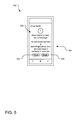
- FIG. 5 illustrates an example prompt relating to receipt of a “stranger” relationship type message.
- FIG. 6 illustrates an example blocking action prompt relating to receipt of a “stranger” relationship type message.
- FIG. 7 illustrates an example non-content-revealing indication of receipt of a “stranger” relationship type call is a recent calls listing.
- FIG. 8 illustrates an example prompt relating to receipt of a “stranger” relationship type call.
- FIG. 9 illustrates an example indication of receipt of a “friend” relationship type message.
- FIG. 10 illustrates an example indication of receipt of a “friend” relationship type message is a recent message listing.
- FIG. 11 illustrates an example messaging screen for a sender having “friend” relationship type with the recipient.
- FIG. 12 illustrates an example indication of receipt of a “friend” relationship type video call.
- FIG. 13 illustrates an example prompt relating to alternative handling of a “friend” relationship type video call.
- FIG. 14 illustrates an example communications service system.
- FIG. 15 illustrates an example relationship qualification service system.
- FIG. 16 illustrates example operations for providing relationship-based communications.
- FIG. 17 illustrates an example system that may be useful in implementing the described technology.
- FIG. 18 illustrates another example system that may be useful in implementing the described technology.
- FIG. 19 is a message sequence chart of one or more processes for controlling communications at a recipient device.
- FIG. 19 A message sequence chart of one or more processes for controlling communications at a recipient device is provided in FIG. 19 , which provides a broad overview of the example equipment, device, and software changes to various systems in the infrastructure.
- FIG. 1 illustrates example entities in a communication system 100 including a relationship qualification service 102 .
- Four users 104 (Adam), 106 (Bill), 108 (Cindy), and 110 (Diane) communicate via a communications service 112 , such as by sending email messages, sending text or instant messages, making telephony or video calls, leaving audio and/or video messages, etc.
- Each user has one or more computing devices though which they can receive communications (e.g., a mobile phone, a tablet computer, a game console, a laptop computer, etc.)
- the communications service 112 which can execute on one or more servers, manages the delivery of such messages to Bill based on a determined relationship type.
- the relationship qualification service 102 which can execute on one or more servers, determines the relationship type between Adam and Bill based on a variety of relevant information, including without limitations, known contacts of Bill, any previous communication history between Adam and Bill (particularly where Bill has responded to Adam, shared contacts, membership in the same enterprise network, etc.). It should be understood that the communications service 112 and the relationship qualification service 102 may be fully or partially integrated (e.g., executing on one or more common servers, being operated by the same service provider) or separate (e.g., executing on completely different servers, being operated by different service providers, etc.).
- message recipients may be protected by a first line of defense in the form of an abuse service 114 , which monitors messages received by the communications service 112 and detects communications abuses (e.g., spam, messages from known malware sources, messages from known phishing sources, etc.). For example, the abuse service 114 may identify the abusive messages to the communications server 112 , which can follow predefined security policies regarding such messages (e.g., blocking the messages, quarantining the messages, etc.)
- the relationship qualification service 102 provides a second line of defense against unwanted interruptions or message content, in this case based upon discernable relationships between the sender and the recipient.
- the relationship qualification service 102 determines a relationship type between the sender and the intended recipient and provides information to allow the communications service 112 to determine how a message is sent from Adam to Bill. For example, if the relationship qualification service 102 collects relevant evidence to satisfy a predefined relationship condition between Bill and Adam to indicate that Adam and Bill have an sufficient relationship to forward the message from the communications service 112 to Bill, then the relationship qualification service 102 can pass the determined relationship type (or some other relevant indication) to the communications service 112 , and the communications service 112 can decide whether and under what conditions to send the message to Bill.
- the relationship qualification service 102 determines that Adam and Bill have a particular relationship type, so the communications service 112 annotates (e.g., tags) the message to indicate the relationship type, or alternatively, to indicate any constraints in the message presentation to Bill. For example, if the relationship qualification service 102 determines that Adam and Bill are “friends” (indicative of there being a high probability that Bill would want to communicate with Adam), then the communications service 112 can annotate the message in a manner that causes Bill's device to provide an interrupting and revealing delivery through its user interface (e.g., an audio alert, a vibration, a visual notification of the message delivery and its contents, etc.). This annotation may simply indicate that the message is to be delivered without constraints.
- the communications service 112 can annotate the message in a manner that causes Bill's device to provide a non-interrupting and non-revealing delivery through its user interface (e.g., no audio alert, no vibration, no visual notification or a minimal visual notification of the message delivery and its contents, etc.). For example, a message from a stranger may simply be delivered into Bill's inbox without alert at all, with only a silent increase in the unread message count, etc. In this manner, Bill is not interrupted by someone with whom he has no discernable relationship.
- the communications service 112 may annotate the message with the relationship type, relying on Bill's device to interpret the relationship type and set the presentation constraints accordingly, possibly with contribution based on enterprise policies and/or Bill's own customized preferences. Alternatively, or in addition, the communications service 112 may annotate the message with specific presentation constraint instructions and/or the relationship type or presentation constraint instructions may be communicated in a separate message to Bill's device.
- the communications service 112 may communicate the inverse of presentation constraints, such as by indicating one or more affirmative user interface behaviors that should be applied by Bill's device upon receipt of the message (e.g., instructing an audio alert and a visual notification, implicitly omitting a vibration), possibly with contribution based on enterprise policies and/or Bill's own customized preferences.
- Other communication methods may be employed.
- FIG. 2 illustrates example communications and entities within a communication system 200 including a relationship qualification service 202 .
- Four users 204 (Adam), 206 (Bill), 208 (Cindy), and 210 (Diane) communicate via a communications service 212 , such as by sending email messages, sending text or instant messages, making telephony or video calls, leaving audio and/or video messages, etc.
- Each user has one or more computing devices though which they can receive communications (e.g., a mobile phone, a tablet computer, a game console, a laptop computer, etc.)
- the entities in FIG. 2 interact to manage the way in which receipt of a communication from a sender is presented to a recipient based on a determined relationship type between the sender and the recipient. Differences in presentation involve different user interface behaviors presented upon receipt that may include without limitation various levels of interrupting or non-interrupting receipt of the communication, a receipt revealing various levels of message content and/or sender-related information, etc.
- an interrupting user interface behavior may provide an audio alert (e.g., a ring), tactile alert (e.g., a vibration), and/or visual (e.g., an alert displayed on the user's screen) alert of receipt.
- another interrupting receipt may omit any audio or tactile alert and only provide a visual alert if the user is active in the user interface (e.g., actively using the mobile device).
- An example of a non-revealing receipt may reveal only the sender's name, phone number, or email address, while the content of the communication is hidden from the recipient until and unless the recipient causes the content to be revealed (e.g., by answering the call, by instructing the recipient's device to reveal the content, etc.).
- the manner of interrupting/non-interrupting receipt and/or the manner of revealing/non-revealing receipt employed at the recipient's device is governed by an annotation attached to or associated with the communication sent by the communications service 212 to the recipient's device.
- the annotation associated with the communication forwarded by the communications service 212 is determined based on a relationship type determined between the sender and the recipient.
- Toasts An example of visual alert is referred to as a “toast,” where the visual alert results in a graphical display that pops up over part of a graphical user interface display at the recipient's device to alert the recipient in a simple, immediate manner of the message receipt.
- Some toasts remain visible for a short period of time before disappearing from view, while others may remain visible until dismissed by the user. Nevertheless, the “toast” does not overly disrupt ongoing use of the recipient's device. Toasts may be considered interrupting behaviors, in that it interrupts the user's visual experience, although different types of toasts may exhibit more interrupting than others (e.g., disappearing versus requiring dismissal).
- the relationship types are determined across a spectrum (e.g., from “stranger” to “friend” or across some other useful range.
- a first sender may be determined to be “family,” and, therefore, communications from the first sender are annotated to provide the most interrupting and/or most revealing user interface behavior (e.g., all hours available for the most interrupting and revealing user interface behavior).
- a second sender may be determined to be a “friend” and, therefore, communications from the second sender may be annotated to provide the most interrupting and revealing user interface behavior when the recipient has determined he or she will likely be awake.
- a third sender may be determined to a “coworker” and, therefore, the level of interruption may be reduced, particularly outside or work hours.
- a fourth sender may be determined to be a “stranger” and, therefore, communications from the fourth sender may be annotated to provide no interrupts and reveal no user content.
- Many other relationship types and associated delivery user interface behavior may be employed, potentially with contribution from enterprise policies and/or the recipient's own customized preferences.
- communication service systems are extended and enhanced to provide a better user experience as various communications are delivered to a recipient.
- This approach allows a recipient's device to provide different user interface behaviors depending on a determined relationship between the sender and the recipient.
- an operating system at the recipient's device (such as a mobile phone) is modified to handle the altered user interface behavior at the recipient's device (e.g., based on the annotation associated with the received communication).
- FIG. 2 An example sequence of communications and operations are shown in FIG. 2 , in a communication between Adam and Bill.
- Adam sends a communication (e.g., a phone call, an instant message, an SMS text message, etc.) in a communication “1” (designated by the circle containing the numeral “1”).
- the communication service 212 employs an abuse service 214 to determine whether Bill or the communication meets the conditions of a known abuse (e.g., spam, malware, etc.).
- a communication may originate from a phone number, an email address, or an IP address that is on a blacklist maintained by the abuse service 214 .
- the communications service 212 may elect to block the communication from Adam (e.g., by not forwarding it to Bill).
- the abuse service 214 may still want to manage its delivery based on his determined relationship with Adam (e.g., managing the level of interruption and/or content provided by the user interface). Accordingly, the communications service 212 queries the relationship qualification service 102 for a relationship type based on one or more descriptors of Bill (e.g., name, email address, phone number, IP address, instant message name, etc.) in an operation “3”. The relationship qualification service 202 returns a relationship type or some other appropriate relationship indicator to the communications service 212 , which annotates the communication accordingly and forwards it to Bill in a communication “4”.
- the relationship qualification service 202 returns a relationship type or some other appropriate relationship indicator to the communications service 212 , which annotates the communication accordingly and forwards it to Bill in a communication “4”.
- the annotation causes Bill's device to present receipt of the communication to Bill by providing one or more interrupting alerts and by revealing at least part of the communication content. Note: In some circumstances, such as a telephony call, there is no content to reveal until Bill answers the call, but in other circumstances, such as an email or text message, a portion of or the entire message may be revealed to Bill upon receipt.
- Bill's reaction to receipt of Adam's communication may be communicated back to the communications service 212 and/or the relationship qualification service 202 to refine the relationship qualification process. For example, regardless of the initial determination of a “friend” relationship between Adam and Bill, if Bill instructs his device to block the call from Adam, the relationship qualification process may be adjusted to always block calls from Adam. Alternatively, implementation of the block on Adam may be offloaded to the communications service 212 or the abuse service 214 .
- FIG. 2 Another example sequence is also shown in FIG. 2 , in a communication between Cindy and Diane.
- Cindy sends a communication (e.g., a phone call, an instant message, an SMS text message, etc.) in a communication “5”.
- the communication service 212 employs an abuse service 214 to determine whether Cindy or the communication meets the conditions of a known abuse (e.g., spam, malware, etc.).
- a communication may originate from a phone number, an email address, or an IP address that is on a blacklist maintained by the abuse service 214 .
- the communications service 212 may elect to block the communication from the Cindy (e.g., by not forwarding it to Diane).
- the abuse service 214 does not determine the communication to be an abuse by the abuse service 214 , the Diane still want to manage its delivery based on her determined relationship with Cindy (e.g., managing the level of interruption and/or content provided by the user interface). Accordingly, the communications service 212 queries the relationship qualification service 102 for a relationship type based on one or more descriptors of Cindy (e.g., name, email address, phone number, IP address, instant message name, etc.) in the operation “3”. The relationship qualification service 202 returns a relationship type or some other appropriate relationship indicator to the communications service 212 , which annotates the communication accordingly and forwards it to Diane in a communication “5”.
- Cindy e.g., managing the level of interruption and/or content provided by the user interface.
- the relationship qualification service 202 returns a relationship type or some other appropriate relationship indicator to the communications service 212 , which annotates the communication accordingly and forwards it to Diane in a communication “5”.
- the annotation causes Diane's device to present receipt of the communication to Diane by silently (e.g., no audio or tactile alert, no interrupting visual notification, only by incrementing the unread message count).
- the relationship qualification process may be adjusted to elevate the relationship between Cindy and Diane from “stranger” to some more accessible level of communications.
- the “block” instructions from Diane may be communicated back to the relationship qualification service 202 , which can adjust the relationship type between Cindy and Diane to some different level (e.g., “blocked stranger).
- implementation of the block between Cindy and Diane may be offloaded to the communications service 212 or the abuse service 214 .
- Other adjustments to the relationship qualification process may be employed. Such feedback may also be provided to the abuse service 214
- the communications service 212 may perform some or all of the functionality of the relationship qualification service 202 (e.g., in that they are integrated or highly cooperative services). For example, the communications service 212 may cache feedback from the recipient, certain source context information, determined relationship types, and use this cached data rather than interacting directly with the relationship qualifications service 202 with each communication. In particular, this approach is efficient in the context of a recipient-authorized communication (e.g., the recipient responded to the source's communication and therefore the communications service 212 can pass communications between the source and the recipient without querying the relationship qualification service 202 ). Furthermore, the abuse service 214 may also perform some or all of the functionality of the relationship qualification service 202 .
- FIG. 3 illustrates an example non-interrupting, non-content-revealing indication 300 of receipt of a “stranger” relationship type communication.
- the mobile device 302 represents a recipient's device in a passive mode (e.g., in the lock screen as opposed to an active mode in which the recipient is actively using an application on the device 302 ).
- the device 302 does not interrupt the recipient with a vibration, a ring, etc. Instead, the receipt is presented through the user interface by incrementing (or in this case, displaying) the count of unread messages.
- the device 302 would likely interrupt the recipient with a vibration, a ring, etc. and could reveal a portion of a message. It should be understood that similar behavior may be exhibited on a tablet computer, a laptop, a desktop computer, a wearable computing device, a gaming console, etc.
- FIG. 4 illustrates an example non-content-revealing indication 400 of receipt of a “stranger” relationship type message is a recent message listing 402 .
- the mobile device 302 represents a recipient's device executing a messaging application.
- a person named “Anna Smith” has attempted to send a message to the recipient, as indicated by indication 400 .
- the communications service and relationship qualification service has determined that available evidence indicates that the Anna Smith is a “stranger” to the recipient, and therefore, in this screen, hides message content from the recipient.
- One justification for this non-revealing presentation is the concept that a “spammer” is successful if a recipient sees the content of a spam message. Accordingly, by hiding the message content sent by a “stranger,” the communications service has thwarted the spammer to some extent.
- the appearance of the indication 400 which differs from the other messages sent by friends, provides the recipient with notice that the associated message is from a sender that has been deemed a “stranger” or at least some sender subject to a non-revealing constraint.
- the indication 400 provides limited information (e.g., the name “Anna Smith”) to give the recipient some indication of the message source, allowing the recipient to decide whether to investigate the message further. To do so, the recipient can select the message (e.g., by touching the message via a touch screen) to access more information about the sender and to manage whether to show the message or block messages from the sender. The recipient may also delete (with or without seeing the message content) through a sequence of user interface actions.
- relationship type determines the relationship type.
- FIG. 4 presents the message indication with significant constraints, showing only the sender's name.
- a relationship type that shows a greater level of anticipated relationship may show a more information in the indication 400 , such as showing a picture of the source, etc.
- the correspondence between the level of constraints and the relationship types may be configured based on hard-coded rules, enterprise policies, user settings, etc.
- relationship types discussed herein are merely examples intended to show a level of perceived relationship or trust the recipient or the relationship qualification service attached to the communication or the source of the communication.
- communication with a “friend” relationship type may be considered a “highly trusted” communication
- communication with a “stranger” relationship type may be considered a “poorly trusted” communication, with an appropriate level of presentation constraint.
- FIG. 5 illustrates an example prompt 500 relating to receipt of a “stranger” relationship type message.
- the mobile device 502 presents the prompt 500 , providing additional information 504 about the sender and/or the recipient's perceived relationship with the sender (collectively referred to as source context information).
- the source context information 504 reveals the sender's email address and the number of contacts the sender and recipient have in common.
- the source context information may be associated with the message (e.g., by being attached to the message as part of an annotation, being sent in a separate communication responsive to the recipient's selection of the message, etc.).
- the recipient may select a “Show” control 506 to show the message content.
- the decision to show the message may be communicated back to the communications service and/or relationship qualification service to provide more information about the recipient's relationship with the sender.
- Selection of the “Show” control presents the message content to the recipient.
- the recipient may select a “Block” control 508 to block future messages from Anna Smith.
- the decision to block messages from Anna Smith may be communicated back to the communications service, the relationship qualification service, or the abuse service to implement future blocks.
- implementation of the blocking may occur locally.
- blocking the message may also delete the message from the message list of FIG. 4 .
- FIG. 6 illustrates an example blocking action prompt 600 relating to receipt of a “stranger” relationship type message.
- selection of the “Block” control 508 of FIG. 5 invokes the prompt 600 to allow the recipient some finer control over the blocking operation.
- the mobile device 602 presents the prompt 600 and offers selection of two options associated with the blocking operation.
- the option 604 if checked when the recipient selects the “Block” control 608 , allows the recipient block all communications (e.g., messages, phone calls, etc.) from the sender. Note: Selecting the “Block” control 608 without selecting the option 604 limits the block to the type of communication received (e.g., messaging in this case).
- the option 606 if check when the recipient selects the “Block” control 608 , allows the recipient report the message as spam. Feedback from both options may be communicated back to the communications service, the relationship qualification service, and/or the abuse service.
- the “Cancel” control 610 takes the recipient back to the prompt 500 of FIG. 5 , without executing a block command.
- another option (not shown) may be presented to allow a recipient to report that the source's account may have been hacked.
- an option (not shown) may be presented to stop interrupting alerts from a source without blocking communications entirely. Such actions may be reported back to the communications service, relationship qualification service, and/or abuse service.
- FIG. 7 illustrates an example non-content-revealing indication 700 of receipt of a “stranger” relationship type call is a recent calls listing 702 .
- the mobile device 704 represents a recipient's device executing a telephony application.
- a person named “Anna Smith” has attempted to call the recipient, as indicated by indication 700 .
- the communications service and relationship qualification service has determined that available evidence indicates that the Anna Smith is a “stranger” to the recipient, and therefore, the recipient was not interrupted with an alert or notification of the receipt. Instead, the call is not answered and/or is sent to voice mail.
- the recipient opens the telephony application on the mobile device 704 , the message and the sender of the messages are displayed in the recent calls list 702 .
- the appearance of the indication 700 which differs from the other recent call sent by friends, provides the recipient with notice that the associated call was from a caller (e.g., a sender) that has been deemed a “stranger” or at least some caller that is subject to a non-interrupting constraint.
- the indication 700 provides limited information (e.g., the name “Anna Smith”) to give the recipient some indication of the call source, allowing the recipient to decide whether to investigate the call further. To do so, the recipient can select the call entry (e.g., by touching the call entry via a touch screen) to access more information about the caller and to manage whether to present a voice or video message from the caller or block calls from the caller. The recipient may also delete (with or without accessing any voice or video message) through a sequence of user interface actions.
- FIG. 8 illustrates an example prompt 800 relating to receipt of a “stranger” relationship type call.
- the mobile device 802 presents the prompt 800 , providing additional information 804 about the caller and/or the recipient's perceived relationship with the caller (collectively referred to as source context information).
- the source context information 804 reveals the caller's email address and the number of contacts the caller and recipient have in common.
- the source context information may be associated with the call (e.g., by being attached to a portion of the call as part of an annotation, being sent in a separate communication responsive to the recipient's selection of the call entry, etc.).
- the recipient may select a “Reply” control 806 to reply to the call.
- the decision to reply to the call may be communicated back to the communications service and/or relationship qualification service to provide more information about the recipient's relationship with the caller.
- Selection of the “reply” control initiates a call to the original caller from the mobile device 802 .
- the recipient may select a “Block” control 808 to block future calls from Anna Smith.
- the decision to block calls from Anna Smith may be communicated back to the communications service, the relationship qualification service, or the abuse service to implement future blocks.
- implementation of the blocking may occur locally.
- blocking the calls may also delete the call entry from the recent calls list of FIG. 7 .
- FIG. 9 illustrates an example indication 900 of receipt of a “friend” relationship type message.
- the mobile device 902 represents a recipient's device in a passive mode (e.g., in the lock screen as opposed to an active mode in which the recipient is actively using an application on the device 902 ).
- the device 902 can interrupt the recipient with a vibration, a ring, etc., present the indication 900 through the user interface by incrementing (or in this case, displaying) the count of unread messages, and further reveal some portion of message content in the banner notification 904 .
- similar behavior may be exhibited on a tablet computer, a laptop, a desktop computer, a wearable computing device, a gaming console, etc.
- FIG. 10 illustrates an example indication 1000 of receipt of a “friend” relationship type message is a recent message listing 1002 .
- the mobile device 1004 represents a recipient's device executing a messaging application.
- a person named “Tom Mix” has attempted to send a message to the recipient, as indicated by indication 1000 .
- the communications service and relationship qualification service has determined that available evidence indicates that the Tom Mix is a “friend” to the recipient, and therefore, in this screen, reveals message content from the recipient.
- the relationship qualification service's determination of the “friend” relationship type between Tom Mix and the recipient may be incorrect.
- the message application may present a “Block” control (not shown) in the screen of FIG. 10 to allow the recipient to easily block future messages from Tom Mix.
- FIG. 11 illustrates an example messaging screen 1100 for a sender having “friend” relationship type with the recipient. If the recipient selects the message from FIG. 10 , then the mobile device 1102 presents the messaging screen 1100 to allow the recipient to respond to the message via input box 1106 . If the recipient responds to the message, the action of responding may be communicated back to the communications service and/or the relationship qualification service to further refine the relationship qualification process.
- the messaging screen 1100 also presents a “Block” control 1104 to allow the recipient to block communications with Tom Mix (e.g., if the recipient discovers that the sender is not the friend he thought the sender was).
- the recipient may select a “Block” control 1104 to block future messages from Tom Mix.
- the decision to block messages from Tom Mix may be communicated back to the communications service, the relationship qualification service, or the abuse service to implement future blocks.
- implementation of the blocking may occur locally.
- blocking the message may also delete the message from the message list of FIG. 10 .
- communications from a source with a high-level relationship type may or may not include such a prominent blocking control 1104 .
- the recipient's device may bury the blocking control 1104 a little deeper in the user interface (e.g., in a drop down menu).
- This example shows yet another type of presentation constraint corresponding to a relationship type within the spectrum of relationship types (e.g., or levels of trust).
- FIG. 12 illustrates an example indication 1200 of receipt of a “friend” relationship type video call.
- the mobile device 1202 presents an available picture of the caller's based on the phone number, communications tag, etc. as part of the indication 1200 .
- the device 1202 can interrupt the recipient with a vibration, a ring, etc., present the indication 1200 through the user interface to alert the recipient of the incoming call. It should be understood that similar behavior may be exhibited on a tablet computer, a laptop, a desktop computer, a wearable computing device, a gaming console, etc.
- the screen with the indication 1200 includes an “Answer” control 1204 , which the recipient may select to answer the video call from Tom Mix.
- the screen with the indication 1200 also includes an “Ignore/Block” control 1206 to allow the recipient to manage how the call is handled. Responsive to selection of the “Ignore/Block” control 1206 , the mobile device 1202 presents a prompt similar to that described with regard to FIG. 13 .
- the screen with the indication 1200 also includes and “Audio” control 1208 to answer the incoming call with audio communications only. Note: In some implementations, communications from a source with a high-level relationship type may or may not include such a prominent “Ignore/Block” control 1206 .
- the recipient's device may bury the “Ignore/Block” control 1206 a little deeper in the user interface (e.g., in a drop down menu).
- This example shows yet another type of presentation constraint corresponding to a relationship type within the spectrum of relationship types (e.g., or levels of trust).
- FIG. 13 illustrates an example prompt 1300 relating to alternative handling of a “friend” relationship type video call.
- selection of the “Ignore/Block” control 1206 of FIG. 12 invokes the prompt 1300 to allow the recipient to manage alternative handling of the video call.
- the mobile device 1302 presents the prompt 1300 and offers selection of several options associated with the ignore/blocking operation.
- the option 1304 if checked when the recipient selects the “Block” control 1306 , allows the recipient block all communications (e.g., messages, phone calls, etc.) from the caller. Note: Selecting the “Block” control 1306 without selecting the option 1304 limits the block to the type of communication received (e.g., messaging in this case).
- the option 1308 if check when the recipient selects the “Block” control 1306 , allows the recipient report the call as spam. Feedback from both options may be communicated back to the communications service, the relationship qualification service, and/or the abuse service.
- the “Cancel” control 1310 takes the recipient back to the screen with the indication 1200 in FIG. 12 , without executing a block command.
- the “Ignore” control 1312 stops any alerts and notifications and allows the call to ring through to a call messaging system.
- another option (not shown) may be presented to allow a recipient to report that the source's account may have been hacked.
- an option (not shown) may be presented to stop interrupting alerts from a source without blocking communications entirely. Such actions may be reported back to the communications service or relationship qualification service.
- the mobile device 1302 also presents additional information 1314 about the caller and/or the recipient's perceived relationship with the caller (collectively referred to as source context information).
- source context information 1314 reveals the caller's email address and the number of contacts the caller and recipient have in common.
- the source context information may be associated with the call (e.g., by being attached to the call as part of an annotation, being sent in a separate communication responsive to the recipient's selection of the call, etc.). Such information can be useful in helping the recipient decide whether to answer, block, or ignore the call.
- FIG. 14 illustrates an example communications service system 1400 .
- a source communication interface 1402 receives communications from a source (e.g., a sender, a caller, etc.) and sends them to a communications sentry 1404 , which manages the handling of the communications.
- the source communication interface 1402 may also send recipient communications back to the source, when and if the recipient decides to respond to the source's communication.
- the communications sentry 1404 receives a communication from the source communication interface 1402 and queries an abuse service via an abuse service interface 1406 . If the abuse service identifies the source or the communication as an abusive communication, the communications sentry 1404 can block communications from the source to the intended recipient.
- the communications sentry 1404 queries a relationship qualification service via a relationship qualification service interface 1408 .
- the relationship qualification service returns to the communications sentry 1404 a relationship type and potentially source context information based on available information (e.g., contacts of both sender and intended recipient, enterprise information, communication history, etc.).
- the communications sentry 1404 annotates the communication based on the relationship type (e.g., to provide presentation constraints, to provide presentation instructions, to provide source context information, etc.) and forward the communication and the annotation to the intended recipient via the recipient communication interface 1406 .
- the recipient communication interface 1406 may also receive recipient communications and pass these communications to the communications sentry 1404 , when and if the recipient decides to respond to the source's communication.
- the recipient communication interface 1406 may also receive feedback from the recipient indicating the recipient's handling of the communication from the source. For example, if the recipient replies to the source, the communications sentry 1404 may forward an indication of such action to the relationship qualification service to refine the relationship qualification process. Likewise, if the recipient ignores a call repeatedly, such information may be communicated through the communications sentry 1404 to the relationship qualification service 1406 to further refine the relationship qualification process. Other such refinements are possible based on received behavior feedback received from the intended recipient via the recipient communication interface 1406 .
- FIG. 15 illustrates an example relationship qualification service system 1500 .
- the relationship qualification service system 1500 receives queries from a communications service system and returns a relationship type, both via a communications service interface 1502 in the illustrated implementation.
- the query may include various source and recipient identifiers, including a name, email address, instant messaging name, phone number, etc. Based on such identifiers, a relationship type investigator 1504 collects information regarding one or both of the source and the recipient to determine a relationship type between the two.
- the available relationship types may span a spectrum (e.g., from “stranger” to “family member”), with two or more relationship types within the spectrum. Different levels of relationship type may correspond to different levels of interrupts and/or content revealing at the recipient's device.
- the relationship type investigator 1504 collects a variety of information and classifies the relationship between the source and the recipient into one of the relationship types. For example, communication history, a source's send-receive rations, a source's block count, etc. can be received via a communications context interface 1506 . Social network relationship and common friends/connections within a social network can be received via a social media interface 1508 . Address book information, phone number information, etc. can be received through an address book interface 1510 . Other interfaces may be employed to gather other relevant relationship information. Some of the collected relationship information may also be communicated to the communications service and on to the recipient (e.g., the number of common contacts, the source's email address, etc.)
- the rules may be evaluated with different weights applied to each rule, based on heuristic, algorithmic, or numerically-determined models, to determine whether the collected information satisfies a particular relationship condition.
- predetermined assortments of rules must be satisfied to meet a particular relationship condition (e.g., a recent communication from the recipient to the source may by itself satisfy a “friend” type by itself, whereas following someone in a microblogging service requires the source to pass other rules, such as a low send-receive ratio and not being blocked by many recipients).
- initial weights may be associated with individual rules, and these weights can be adjusted based on the number of blocks, replies, ignores, and other relationship qualification information received by the communications service and the relationship qualification service.
- FIG. 16 illustrates example operations 1600 for providing relationship-based communications.
- a receiving operation 1602 receives a communication from a source (e.g., a message sender, a caller, etc.) to a recipient with a computing device on which the recipient can receive the communication.
- a collection operation 1604 collects relationship information about the source and/or the recipient.
- a determining operation 1606 determines a relationship type between the source and the recipient based on at least some of the collected relationship data.
- An annotation operation 1608 annotates the communication to affect how receipt of the communication by the recipient's device will be presented to the recipient through its user interface.
- the annotation may include without limitation a relationship type, presentation constraints or instructions, source context information, etc.
- the annotated communication is referred to a “relationship-qualified version of the communication” because it has been annotated based on the relationship type determined between the source and the recipient.
- a sending operation 1610 forwards the relationship-qualified version of the communication to the recipient, where the annotation causes certain user interface behavior to be presented to the recipient through the recipient's device.
- An updating operation 1612 updates the relationship information available to a relationship qualification service based on feedback from the recipient's management of the received communication. For example, if the recipient replies to the communication, then the communication history is updated. If the recipient blocks communications from the source, then the block count is updated. Other such updates may be employed based on the recipient's management of the communication.
- FIG. 17 illustrates an example system that may be useful in implementing the described technology.
- the example hardware and operating environment of FIG. 17 for implementing the described technology includes a computing device, such as general purpose computing device in the form of a gaming console or computer 20 , a mobile telephone, a personal data assistant (PDA), a set top box, or other type of computing device.
- the computer 20 includes a processing unit 21 , a system memory 22 , and a system bus 23 that operatively couples various system components including the system memory to the processing unit 21 .
- the processor of computer 20 may be only one or there may be more than one processing unit 21 , such that the processor of computer 20 comprises a single central-processing unit (CPU), or a plurality of processing units, commonly referred to as a parallel processing environment.
- the computer 20 may be a conventional computer, a distributed computer, or any other type of computer; the invention is not so limited.
- the system bus 23 may be any of several types of bus structures including a memory bus or memory controller, a peripheral bus, a switched fabric, point-to-point connections, and a local bus using any of a variety of bus architectures.
- the system memory may also be referred to as simply the memory, and includes read only memory (ROM) 24 and random access memory (RAM) 25 .
- ROM read only memory
- RAM random access memory
- a basic input/output system (BIOS) 26 containing the basic routines that help to transfer information between elements within the computer 20 , such as during start-up, is stored in ROM 24 .
- the computer 20 further includes a hard disk drive 27 for reading from and writing to a hard disk, not shown, a magnetic disk drive 28 for reading from or writing to a removable magnetic disk 29 , and an optical disk drive 30 for reading from or writing to a removable optical disk 31 such as a CD ROM, DVD, or other optical media.
- a hard disk drive 27 for reading from and writing to a hard disk, not shown
- a magnetic disk drive 28 for reading from or writing to a removable magnetic disk 29
- an optical disk drive 30 for reading from or writing to a removable optical disk 31 such as a CD ROM, DVD, or other optical media.
- the hard disk drive 27 , magnetic disk drive 28 , and optical disk drive 30 are connected to the system bus 23 by a hard disk drive interface 32 , a magnetic disk drive interface 33 , and an optical disk drive interface 34 , respectively.
- the drives and their associated computer-readable media provide nonvolatile storage of computer-readable instructions, data structures, program modules and other data for the computer 20 . It should be appreciated by those skilled in the art that any type of computer-readable media which can store data that is accessible by a computer, such as magnetic cassettes, flash memory cards, digital video disks, random access memories (RAMs), read only memories (ROMs), and the like, may be used in the example operating environment.
- a number of program modules may be stored on the hard disk, magnetic disk 29 , optical disk 31 , ROM 24 , or RAM 25 , including an operating system 35 , one or more application programs 36 , other program modules 37 , and program data 38 .
- a user may enter commands and information into the personal computer 20 through input devices such as a keyboard 40 and pointing device 42 .
- Other input devices may include a microphone, joystick, game pad, satellite dish, scanner, or the like.
- These and other input devices are often connected to the processing unit 21 through a serial port interface 46 that is coupled to the system bus, but may be connected by other interfaces, such as a parallel port, game port, or a universal serial bus (USB).
- a monitor 47 or other type of display device is also connected to the system bus 23 via an interface, such as a video adapter 48 .
- computers typically include other peripheral output devices (not shown), such as speakers and printers.
- the computer 20 may operate in a networked environment using logical connections to one or more remote computers, such as remote computer 49 . These logical connections are achieved by a communication device coupled to or a part of the computer 20 ; the invention is not limited to a particular type of communications device.
- the remote computer 49 may be another computer, a server, a router, a network PC, a client, a peer device or other common network node, and typically includes many or all of the elements described above relative to the computer 20 , although only a memory storage device 50 has been illustrated in FIG. 17 .
- the logical connections depicted in FIG. 17 include a local-area network (LAN) 51 and a wide-area network (WAN) 52 .
- LAN local-area network
- WAN wide-area network
- Such networking environments are commonplace in office networks, enterprise-wide computer networks, intranets and the Internet, which are all types of networks.
- the computer 20 When used in a LAN-networking environment, the computer 20 is connected to the local network 51 through a network interface or adapter 53 , which is one type of communications device.
- the computer 20 When used in a WAN-networking environment, the computer 20 typically includes a modem 54 , a network adapter, a type of communications device, or any other type of communications device for establishing communications over the wide area network 52 .
- the modem 54 which may be internal or external, is connected to the system bus 23 via the serial port interface 46 .
- program engines depicted relative to the personal computer 20 may be stored in the remote memory storage device. It is appreciated that the network connections shown are example and other means of and communications devices for establishing a communications link between the computers may be used.
- one or more communication services, one or more application services, an abuse service, and other engines and services may be embodied by instructions stored in memory 22 and/or storage devices 29 or 31 and processed by the processing unit 21 .
- Address books, communication histories, information about a user's social network, and other data may be stored in memory 22 and/or storage devices 29 or 31 as persistent datastores.
- a service server represents hardware and/or software configured to provide service functionality for network-connected systems.
- Such services may be implemented using a general purpose computer and specialized software (such as a server executing service software), a special purpose computing system and specialized software (such as a mobile device or network appliance executing service software), or other computing configurations.
- module may be used to describe an aspect of computing system 20 that is implemented to perform one or more particular functions.
- a module, program, service, or engine may be instantiated via processing unit 21 executing instructions held by system memory 22 .
- different modules, programs, and/or engines may be instantiated from the same application, service, code block, object, library, routine, API, function, etc.
- the same module, program, and/or engine may be instantiated by different applications, services, code blocks, objects, routines, APIs, functions, etc.
- module program
- engine are meant to encompass individual or groups of executable files, data files, libraries, drivers, scripts, database records, etc.
- FIG. 18 illustrates another example system (labeled as a mobile device 1800 ) that may be useful in implementing the described technology.
- the mobile device 1800 includes a processor 1802 , a memory 1804 , a display 1806 (e.g., a touchscreen display), and other interfaces 1808 (e.g., a keyboard).
- the memory 1804 generally includes both volatile memory (e.g., RAM) and non-volatile memory (e.g., flash memory).
- An operating system 1810 such as the Microsoft Windows® Phone operating system, resides in the memory 1804 and is executed by the processor 1802 , although it should be understood that other operating systems may be employed.
- One or more application programs 1812 are loaded in the memory 1804 and executed on the operating system 1810 by the processor 1802 .
- applications 1812 include without limitation email programs, scheduling programs, personal information managers, Internet browsing programs, multimedia player applications, etc.
- a notification manager 1814 is also loaded in the memory 1804 and is executed by the processor 1802 to present notifications to the user. For example, when a communication is received, the notification manager 1814 can cause the mobile device 1800 to beep or vibrate (via the vibration device 1818 ) and display the notification and/or message content on the display 1806 .
- the mobile device 1800 includes a power supply 1816 , which is powered by one or more batteries or other power sources and which provides power to other components of the mobile device 1800 .
- the power supply 1816 may also be connected to an external power source that overrides or recharges the built-in batteries or other power sources.
- the mobile device 1800 includes one or more communication transceivers 1830 to provide network connectivity (e.g., mobile phone network, Wi-Fi®, BlueTooth®, etc.).
- the mobile device 1800 also includes various other components, such as a positioning system 1820 (e.g., a global positioning satellite transceiver), one or more accelerometers 1822 , one or more cameras 1824 , an audio interface 1826 (e.g., a microphone, an audio amplifier and speaker and/or audio jack), and additional storage 1828 . Other configurations may also be employed.
- a one or more communication services, one or more application services, an abuse service and other engines and services may be embodied by instructions stored in memory 1804 and/or storage devices 1828 and processed by the processing unit 1802 .
- Address books, communication histories, information about a user's social network, and other data may be stored in memory 1804 and/or storage devices 1828 as persistent datastores.
- Mobile device 1800 and computer 20 may include a variety of tangible computer-readable storage media and intangible computer-readable communication signals.
- Tangible computer-readable storage can be embodied by any available media that can be accessed by the mobile device 1800 or the computer 20 and includes both volatile and nonvolatile storage media, removable and non-removable storage media.
- Tangible computer-readable storage media excludes intangible communications signals and includes volatile and nonvolatile, removable and non-removable storage media implemented in any method or technology for storage of information such as computer readable instructions, data structures, program modules or other data.
- Tangible computer-readable storage media includes, but is not limited to, RAM, ROM, EEPROM, flash memory or other memory technology, CDROM, digital versatile disks (DVD) or other optical disk storage, magnetic cassettes, magnetic tape, magnetic disk storage or other magnetic storage devices, or any other tangible medium which can be used to store the desired information and which can accessed by mobile device 1800 or computer 20 .
- intangible computer-readable communication signals may embody computer readable instructions, data structures, program modules or other data resident in a modulated data signal, such as a carrier wave or other signal transport mechanism.
- modulated data signal means a signal that has one or more of its characteristics set or changed in such a manner as to encode information in the signal.
- FIG. 19 is a message sequence chart of one or more processes for controlling communications at a recipient device (such as video calls, instant messages and others) at a recipient device 1910 (such as a smart phone, tablet computer, or other end user computing equipment).
- the recipient device 1910 (and/or the sender device 1922 ) may be resource constrained in terms of having one or more of limited: memory, battery power, computing resource, etc. It should be understood that communication control described herein may be implemented to accommodate resource constraints of the recipient device 1910 , the sender device 1922 , and/or other devices in the end-to-end communications system.
- the recipient device 1910 may comprise a communications application 1912 implemented using software and/or hardware at the recipient device 1910 and arranged to interact with a remote communications server 1920 , for example, in the a communication network, storage network, and/or computing network (e.g., the “cloud”).
- the communications application 1912 may, together with the communications server, provide synchronous communications, such as voice over internet protocol, video calls, instant messaging and others. It is also possible for the communications application 1912 together with the communications server to provide asynchronous communications, such as email, short message service (SMS) and others.
- SMS short message service
- Communications control for the recipient device enables a trade-off between participating in potential new communications and guarding against unwanted communications to be automatically adjusted. This approach is particularly useful for synchronous communications where it is typically more difficult for this trade off to be controlled dynamically due to the immediate nature of the communications.
- the recipient device 1910 may receive synchronous communication from a sender equipment/device 1922 with which the recipient device 1910 has not previously established synchronous communication. This may be achieved, for example, by sending messages annotated with instructions and/or data to the recipient device. The recipient device is arranged to control its communications behavior on the basis of the annotated messages.
- the annotated messages are annotated push notifications as now described with reference to FIG. 19 .
- This is especially useful for synchronous communications as it is possible to immediately use an existing, persistent notification channel to send toast messages, update tiles and to send raw data (without the need to open a new communications channel). Even where the communications application is not executing on the recipient device push notifications may be received. This conserves battery power at the recipient device. Having said that, it is not essential to use a push notification server as indicated in FIG. 19 . In that case, the communications server 1920 is used to send the annotated messages to the recipient device, by opening a new communications channel with the recipient device.
- an operating system 1914 at the recipient device may be modified to interpret annotated push notifications so as to control communications behavior at the recipient device resulting in a dynamically controlled trade-off as mentioned above.
- the push notifications are actionable push notifications, whereby the operating system of the recipient device may reply to a push notification server. This conserves battery and/or computing resource at the recipient device, for example, where an end user makes input indicating that a requested communication from a sender is to be denied or delayed. That user input may be communicated on the notification channel without the need to open the communications application 1912 at the recipient device 1910 .
- some or all of the push notification server functionality may be handled by changes by the operating system control in the recipient device 1910 and/or the sender device 1922 .
- a push notification server 1916 in combination with a relationship server 1918 and a communications server 1920 , it is possible to take the burden of dynamic control of the trade-off mentioned above away from the recipient device 1910 . This is especially useful where the recipient device 1910 is resource-constrained.
- the message sequence chart of FIG. 19 represents each of the recipient device 1910 , a push notification server 1916 , a relationship server 1918 , a communications server 1920 and a sender device 1922 as vertical lines on the page. Messages sent between these entities are represented by horizontal arrows where the relative position of the arrows vertically on the page represents chronological order of the messages.
- the push notification server 1916 , relationship server 1918 and communications server 1920 are computer implemented using software and/or hardware.
- the push notification server 1916 , relationship server 1918 and communications server 1920 may be integral with one another, in whole or in part.
- the sender device 1922 may be a mobile phone, tablet computer or any other end user device capable of communicating with the recipient device 1910 and the communications server 1920 .
- a persistent push notification channel 1924 exists between the recipient device operating system 1914 and a push notification server 1916 .
- the endpoint (such as a URI) of the push notification channel is known to the communications server 1920 .
- a sender device 1922 desires to make a communication, such as a video call or an instant message communication, with recipient device 1910 .
- the sender device 1922 may not have previously established a synchronous communication with the recipient device 1910 .
- the sender device 1922 sends a request message 1926 to the communications server 1920 to request synchronous communication with recipient device 1910 .
- the communications server 1920 sends a notification message to the endpoint of the persistent notification channel at the push notification server 1916 .
- the push notification server 1916 sends a request 1930 to a relationship server 1918 to request data about any relationship between the sender device and the recipient device. More detail about the relationship server and the data is given below.
- the relationship server 1918 is part of the relationship service described in the examples below.
- the relationship server 1918 sends data 1932 to the push notification server about the relationship.
- the data may be in the form of a numerical score, a rating, thresholds, criteria, rules, raw data or others.
- the push notification server 1916 annotates 1934 the notification message and forwards the annotated notification message to the recipient device operating system 1914 using the existing persistent notification channel.
- the push notification server 1916 retrieves the relationship data and annotates the notification message.
- the communications server it is also possible for the communications server to carry out one or both of these steps.
- the annotations to the notification message are stored in a payload of the push notification message.
- the annotations may comprise the relationship data.
- the annotations comprise instructions to be executed by the recipient device operating system 1914 .
- the annotations comprise both relationship data and instructions to be executed by the recipient device operating system 1914 .
- the operating system 1914 of the recipient device 1910 receives the annotated notification message 1936 . It extracts the annotation from the payload and recognizes the annotation as being for controlling communications. It executes 1938 the notification on the basis of the annotation.
- the annotation comprises relationship data, such as a numerical score
- the operating system selects between a plurality of actions on the basis of the score. The actions may depend on whether the communications application 1912 is already executing at the recipient device 1910 or not.
- the actions may comprise, allowing/disallowing a toast message, allowing a toast message and adding relationship data from the annotation into the toast message, allowing/disallowing an audible alert, allowing/disallowing a tactile alert.
- the actions may comprise sending/not sending the notification message to the application.
- the recipient device 1910 may receive user input 1940 .
- the user input may be communicated to the push notification server 1916 using the persistent notification channel 1924 where the communications application 1912 is not already executing for example. This is shown as actionable notification 1942 in FIG. 19 .
- the push notification server forwards the user input to the communications server 1922 using message 1944 .
- Communications server 1922 informs sender device 1922 using message 1946 .
- a synchronous communications channel (such as a video call or instant messaging channel) may be established between the recipient device 1910 and sender device 1922 as shown by arrow 1948 .
- the communications application 1912 may send a message 1950 to the communications server 1920 using a channel it already has open with the communications server 1920 .
- the communications server 1920 informs the sender device 1922 using message 1952 .
- a communications channel such as a video channel or instant message channel, may be opened between the recipient device 1910 and the sender device 1922 as shown by arrow 1954 .
- a recipient communications device comprises: an operating system arranged to receive an annotated notification message on a persistent notification channel established with a notification server, the notification message comprising a request from a sending device to establish a communication with the recipient communications device; the operating system being arranged to execute the notification message on the basis of the annotation so as to control the requested communication.
- the requested communication may be a synchronous communication.
- a communications server (or notification server) comprises: a processor arranged to receive a notification message requesting a communication between a sending device and a recipient device; a memory storing data about a relationship between the sending device and the recipient device; the processor being arranged to annotate the notification message using the stored data and to send the annotated notification message to the recipient device.
- annotations to a notification messages may be fetched from the communications service, abuse service, relationship qualification service, and/or push notification service independently or separately from the communication of the notification message or other communications.
- the payload packaging of communication messages and annotations may take a variety of forms.
- the embodiments of the invention described herein are implemented as logical steps in one or more computer systems.
- the logical operations of the present invention are implemented (1) as a sequence of processor-implemented steps executing in one or more computer systems and (2) as interconnected machine or circuit engines within one or more computer systems.
- the implementation is a matter of choice, dependent on the performance requirements of the computer system implementing the invention. Accordingly, the logical operations making up the embodiments of the invention described herein are referred to variously as operations, steps, objects, or engines.
- logical operations may be performed in any order, unless explicitly claimed otherwise or a specific order is inherently necessitated by the claim language.
Abstract
Description
-
- Address Book Match—Does the source identifier match an entry in the recipient's address book(s)?
- Phone Number Validation—(a) Does source have a verified phone number and (b) does source have recipient's phone number in source's address book?
- Communication History—Is there evidence that recipient has ever communicated (e.g., emailed, called, instant messaged, texted, etc.) the source?
- Sharing—Are source and recipient sharing documents within a document sharing system?
- Public Access—Has recipient indicated that he/she wants the public to have unconstrained deliver access to his/her device?
- Physical Network—Are source and recipient on the same physical wired network?
- Social Network—Are source and recipient already connected or “friends” in a social network?
- Work Domain—Are source and recipient within the same work (e.g., private) domain?
- Shared Contacts—How many common contacts to the source and recipient have between them?
- Send-receive Ratios—Does the source have a high ratio of sent communications compared to received communications with other recipients?
- Many Blocks—Does the source have a high number of recipients already blocked the source?
Claims (22)
Priority Applications (2)
| Application Number | Priority Date | Filing Date | Title |
|---|---|---|---|
| US14/193,443 US9772985B2 (en) | 2014-02-28 | 2014-02-28 | Communications control for resource constrained devices |
| PCT/US2015/017613 WO2015130857A1 (en) | 2014-02-28 | 2015-02-26 | Communications control for resource constrained devices |
Applications Claiming Priority (1)
| Application Number | Priority Date | Filing Date | Title |
|---|---|---|---|
| US14/193,443 US9772985B2 (en) | 2014-02-28 | 2014-02-28 | Communications control for resource constrained devices |
Publications (2)
| Publication Number | Publication Date |
|---|---|
| US20150248389A1 US20150248389A1 (en) | 2015-09-03 |
| US9772985B2 true US9772985B2 (en) | 2017-09-26 |
Family
ID=52693042
Family Applications (1)
| Application Number | Title | Priority Date | Filing Date |
|---|---|---|---|
| US14/193,443 Active 2034-12-04 US9772985B2 (en) | 2014-02-28 | 2014-02-28 | Communications control for resource constrained devices |
Country Status (2)
| Country | Link |
|---|---|
| US (1) | US9772985B2 (en) |
| WO (1) | WO2015130857A1 (en) |
Cited By (2)
| Publication number | Priority date | Publication date | Assignee | Title |
|---|---|---|---|---|
| US10992633B1 (en) * | 2018-12-31 | 2021-04-27 | Whatsapp Inc. | Methods and systems for determining an unread message count |
| US11182051B2 (en) | 2017-02-08 | 2021-11-23 | Alibaba Group Holding Limited | Instant communication message prompting method and instant communication client |
Families Citing this family (34)
| Publication number | Priority date | Publication date | Assignee | Title |
|---|---|---|---|---|
| USD786267S1 (en) * | 2014-03-28 | 2017-05-09 | Razer (Asia-Pacific) Pte. Ltd. | Display screen with graphical user interface |
| CN105099853A (en) * | 2014-04-25 | 2015-11-25 | 国际商业机器公司 | Erroneous message sending preventing method and system |
| US11343335B2 (en) | 2014-05-29 | 2022-05-24 | Apple Inc. | Message processing by subscriber app prior to message forwarding |
| US9207835B1 (en) | 2014-05-31 | 2015-12-08 | Apple Inc. | Message user interfaces for capture and transmittal of media and location content |
| US10382378B2 (en) | 2014-05-31 | 2019-08-13 | Apple Inc. | Live location sharing |
| US10126924B1 (en) * | 2014-06-20 | 2018-11-13 | Path Mobile Inc Pte. Ltd. | Efficient transmission of predefined messages in a messaging environment |
| WO2016022496A2 (en) | 2014-08-06 | 2016-02-11 | Apple Inc. | Reduced-size user interfaces for battery management |
| CN115623117A (en) | 2014-09-02 | 2023-01-17 | 苹果公司 | Telephone user interface |
| JP6349030B2 (en) | 2014-09-02 | 2018-06-27 | アップル インコーポレイテッド | Small interface for managing alerts |
| US10237220B2 (en) * | 2015-07-24 | 2019-03-19 | Facebook, Inc. | Techniques to promote filtered messages based on historical reply rate |
| US10003938B2 (en) | 2015-08-14 | 2018-06-19 | Apple Inc. | Easy location sharing |
| JP6580903B2 (en) * | 2015-08-28 | 2019-09-25 | 京セラ株式会社 | Portable electronic devices |
| US10345986B1 (en) * | 2016-05-17 | 2019-07-09 | Google Llc | Information cycling in graphical notifications |
| USD842336S1 (en) | 2016-05-17 | 2019-03-05 | Google Llc | Display screen with animated graphical user interface |
| US9654622B1 (en) * | 2016-10-05 | 2017-05-16 | Google Inc. | Automatically altering characteristics of audio alerts |
| US11171905B1 (en) * | 2016-10-17 | 2021-11-09 | Open Invention Network Llc | Request and delivery of additional data |
| US20180367492A1 (en) * | 2017-06-19 | 2018-12-20 | Microsoft Technology Licensing, Llc | Providing notification based on dynamic group |
| US10524010B2 (en) * | 2017-11-07 | 2019-12-31 | Facebook, Inc. | Social interaction user interface for videos |
| USD861025S1 (en) * | 2018-01-23 | 2019-09-24 | Whatsapp Inc. | Display screen with an animated graphical user interface |
| USD870742S1 (en) | 2018-01-26 | 2019-12-24 | Facebook, Inc. | Display screen or portion thereof with animated user interface |
| US10965630B2 (en) | 2018-08-03 | 2021-03-30 | Flash App, LLC | Enhanced data sharing to and between mobile device users |
| USD947233S1 (en) * | 2018-12-21 | 2022-03-29 | Streamlayer, Inc. | Display screen or portion thereof with transitional graphical user interface |
| USD997952S1 (en) | 2018-12-21 | 2023-09-05 | Streamlayer, Inc. | Display screen with transitional graphical user interface |
| US11770579B2 (en) | 2018-12-21 | 2023-09-26 | Streamlayer, Inc. | Method and system for providing interactive content delivery and audience engagement |
| WO2020243639A1 (en) * | 2019-05-31 | 2020-12-03 | Apple Inc. | Device-relationship based communication |
| US11481094B2 (en) | 2019-06-01 | 2022-10-25 | Apple Inc. | User interfaces for location-related communications |
| US11152100B2 (en) | 2019-06-01 | 2021-10-19 | Apple Inc. | Health application user interfaces |
| US11477609B2 (en) | 2019-06-01 | 2022-10-18 | Apple Inc. | User interfaces for location-related communications |
| USD985579S1 (en) * | 2021-03-05 | 2023-05-09 | Mobiline, Inc. | Smartphone display with personalized video invitations graphical user interface |
| USD985007S1 (en) * | 2021-03-05 | 2023-05-02 | Mobiline, Inc. | Smartphone display with missed call graphical user interface |
| USD985017S1 (en) * | 2021-03-05 | 2023-05-02 | Mobiline, Inc. | Smartphone display with personalized audio invitation graphical user interface |
| USD989802S1 (en) * | 2021-03-05 | 2023-06-20 | Mobiline, Inc. | Smartphone display with missed call graphical user interface |
| USD989775S1 (en) * | 2021-03-05 | 2023-06-20 | Mobiline, Inc. | Smartphone display with personalized video invitation graphical user interface |
| USD985012S1 (en) * | 2021-03-05 | 2023-05-02 | Mobiline, Inc. | Smartphone display with personalized audio invitations graphical user interface |
Citations (42)
| Publication number | Priority date | Publication date | Assignee | Title |
|---|---|---|---|---|
| US20050160292A1 (en) * | 2004-01-21 | 2005-07-21 | Microsoft Corporation | Encryption to BCC recipients with S/MIME |
| US20070014280A1 (en) | 2005-07-13 | 2007-01-18 | Research In Motion Limited | Customizability of event notification on telephony-enabled devices |
| US20070203993A1 (en) * | 2006-02-28 | 2007-08-30 | Yigang Cai | Instant messaging control |
| US20080148154A1 (en) * | 2006-12-14 | 2008-06-19 | Microsoft Corporation | Dynamic information publication enabling direct access to a preferred communication channel connection in integrated communication server |
| US20080182556A1 (en) * | 2007-01-30 | 2008-07-31 | Datasci, Llc | Systems and methods for filtering cellular telephone messages |
| US20080256602A1 (en) * | 2007-04-11 | 2008-10-16 | Pagan William G | Filtering Communications Between Users Of A Shared Network |
| US20090037350A1 (en) * | 2007-01-18 | 2009-02-05 | Jubii Ip Limited | Method for automatically displaying electronic information received by a recipient in a sorted order and a communication system and/or system for exchanging information |
| US7509385B1 (en) * | 2008-05-29 | 2009-03-24 | International Business Machines Corporation | Method of system for creating an electronic message |
| US7512652B1 (en) * | 2001-09-28 | 2009-03-31 | Aol Llc, A Delaware Limited Liability Company | Passive personalization of buddy lists |
| US20090132655A1 (en) | 2006-10-26 | 2009-05-21 | Philip Behrens | Method, system and device for controlling and/or limiting electronic communication |
| US20090177744A1 (en) * | 2008-01-04 | 2009-07-09 | Yahoo! Inc. | Identifying and employing social network relationships |
| US20090182832A1 (en) | 2008-01-16 | 2009-07-16 | International Business Machines Corporation | Social collaborative scoring for message prioritization based upon an organizational relationship between sender and recipient |
| US20090210497A1 (en) | 2008-02-14 | 2009-08-20 | International Business Machines Corporation | Selective instant messaging (im) notifications based on sender/receiver relationships |
| US20100030858A1 (en) * | 2008-08-04 | 2010-02-04 | Chasin C Scott | Method and system for centralized contact management |
| US20100281113A1 (en) | 2009-04-29 | 2010-11-04 | Nokia Corporation | Method and apparatus for automatically matching contacts |
| US20100285843A1 (en) * | 2004-12-01 | 2010-11-11 | Aol Inc. | Prohibiting mobile forwarding |
| US7885901B2 (en) | 2004-01-29 | 2011-02-08 | Yahoo! Inc. | Method and system for seeding online social network contacts |
| US20110173274A1 (en) * | 2008-06-13 | 2011-07-14 | Messagemind, Inc. | Method and system for mapping organizational social networks utilizing dynamically prioritized e-mail flow indicators |
| US20110184937A1 (en) * | 2010-01-26 | 2011-07-28 | International Business Machines Corporation | System and method for selective information and resource sharing |
| US8060573B2 (en) | 2008-11-20 | 2011-11-15 | MeetMyKind, LLC | Matching social network users |
| US20120198002A1 (en) | 2011-01-27 | 2012-08-02 | T-Mobile Usa, Inc. | Unified Notification Platform |
| US20120196581A1 (en) | 2011-01-31 | 2012-08-02 | Matthew Nicholas Papakipos | Caller Identification Using Social Network Information |
| US20120214456A1 (en) * | 2011-02-22 | 2012-08-23 | Samsung Electronics Co., Ltd. | Methods and apparatus for transmitting data |
| US20120254229A1 (en) * | 2011-04-04 | 2012-10-04 | Uri Raz | Determining potential relationships between individuals |
| US20120278388A1 (en) * | 2010-12-30 | 2012-11-01 | Kyle Kleinbart | System and method for online communications management |
| US20130084835A1 (en) * | 2006-05-25 | 2013-04-04 | Wefi, Inc. | Method and System for Selecting a Wireless Network for Offloading |
| US8447967B1 (en) * | 2000-06-29 | 2013-05-21 | Datamotion, Inc. | Controlled message distribution |
| US20130143608A1 (en) * | 2011-12-06 | 2013-06-06 | Hon Hai Precision Industry Co., Ltd. | Mobile phone for processing short messages and method thereof |
| US20130166555A1 (en) * | 2011-12-22 | 2013-06-27 | Nokia Corporation | Method and apparatus for managing contact data by utilizing social proximity information |
| US20130246449A1 (en) * | 2012-03-16 | 2013-09-19 | Research In Motion Limited | Methods and devices for identifying a relationship between contacts |
| US20130295973A1 (en) | 2012-05-02 | 2013-11-07 | Cisco Technology, Inc. | Method and apparatus for managing interruptions from different modes of communication |
| US20130316746A1 (en) * | 2012-05-27 | 2013-11-28 | Qualcomm Incorporated | Personal hub presence and response |
| US20130326221A1 (en) * | 2012-06-04 | 2013-12-05 | Private Giant | Confidential Message Exchange Using Benign, Context-Aware Cover Message Generation |
| US20130339436A1 (en) * | 2012-06-19 | 2013-12-19 | Research In Motion Limited | Delayed or suspended alerts with multiple devices in proximity |
| US20130339276A1 (en) * | 2012-02-10 | 2013-12-19 | International Business Machines Corporation | Multi-tiered approach to e-mail prioritization |
| US20140059693A1 (en) * | 2012-08-22 | 2014-02-27 | Mcafee, Inc. | Anonymous shipment brokering |
| US20140066063A1 (en) * | 2012-08-30 | 2014-03-06 | Samsung Electronics Co., Ltd. | Heartbeat period determination method and apparatus for push service in wireless network |
| US20140189030A1 (en) * | 2012-12-28 | 2014-07-03 | Hayat Benchenaa | Displaying notifications on a mobile computing device |
| US20140188846A1 (en) * | 2012-10-12 | 2014-07-03 | Empire Technology Development Llc | Data list customization based on social relationship |
| US20140229980A1 (en) | 2006-08-04 | 2014-08-14 | Aol Inc. | Mechanism for rendering advertising objects into featured content |
| US20150024793A1 (en) * | 2013-07-18 | 2015-01-22 | International Business Machines Corporation | Push notification middleware |
| US20150135096A1 (en) * | 2013-11-14 | 2015-05-14 | Avaya Inc. | System and method for displaying context-aware contact details |
-
2014
- 2014-02-28 US US14/193,443 patent/US9772985B2/en active Active
-
2015
- 2015-02-26 WO PCT/US2015/017613 patent/WO2015130857A1/en active Application Filing
Patent Citations (42)
| Publication number | Priority date | Publication date | Assignee | Title |
|---|---|---|---|---|
| US8447967B1 (en) * | 2000-06-29 | 2013-05-21 | Datamotion, Inc. | Controlled message distribution |
| US7512652B1 (en) * | 2001-09-28 | 2009-03-31 | Aol Llc, A Delaware Limited Liability Company | Passive personalization of buddy lists |
| US20050160292A1 (en) * | 2004-01-21 | 2005-07-21 | Microsoft Corporation | Encryption to BCC recipients with S/MIME |
| US7885901B2 (en) | 2004-01-29 | 2011-02-08 | Yahoo! Inc. | Method and system for seeding online social network contacts |
| US20100285843A1 (en) * | 2004-12-01 | 2010-11-11 | Aol Inc. | Prohibiting mobile forwarding |
| US20070014280A1 (en) | 2005-07-13 | 2007-01-18 | Research In Motion Limited | Customizability of event notification on telephony-enabled devices |
| US20070203993A1 (en) * | 2006-02-28 | 2007-08-30 | Yigang Cai | Instant messaging control |
| US20130084835A1 (en) * | 2006-05-25 | 2013-04-04 | Wefi, Inc. | Method and System for Selecting a Wireless Network for Offloading |
| US20140229980A1 (en) | 2006-08-04 | 2014-08-14 | Aol Inc. | Mechanism for rendering advertising objects into featured content |
| US20090132655A1 (en) | 2006-10-26 | 2009-05-21 | Philip Behrens | Method, system and device for controlling and/or limiting electronic communication |
| US20080148154A1 (en) * | 2006-12-14 | 2008-06-19 | Microsoft Corporation | Dynamic information publication enabling direct access to a preferred communication channel connection in integrated communication server |
| US20090037350A1 (en) * | 2007-01-18 | 2009-02-05 | Jubii Ip Limited | Method for automatically displaying electronic information received by a recipient in a sorted order and a communication system and/or system for exchanging information |
| US20080182556A1 (en) * | 2007-01-30 | 2008-07-31 | Datasci, Llc | Systems and methods for filtering cellular telephone messages |
| US20080256602A1 (en) * | 2007-04-11 | 2008-10-16 | Pagan William G | Filtering Communications Between Users Of A Shared Network |
| US20090177744A1 (en) * | 2008-01-04 | 2009-07-09 | Yahoo! Inc. | Identifying and employing social network relationships |
| US20090182832A1 (en) | 2008-01-16 | 2009-07-16 | International Business Machines Corporation | Social collaborative scoring for message prioritization based upon an organizational relationship between sender and recipient |
| US20090210497A1 (en) | 2008-02-14 | 2009-08-20 | International Business Machines Corporation | Selective instant messaging (im) notifications based on sender/receiver relationships |
| US7509385B1 (en) * | 2008-05-29 | 2009-03-24 | International Business Machines Corporation | Method of system for creating an electronic message |
| US20110173274A1 (en) * | 2008-06-13 | 2011-07-14 | Messagemind, Inc. | Method and system for mapping organizational social networks utilizing dynamically prioritized e-mail flow indicators |
| US20100030858A1 (en) * | 2008-08-04 | 2010-02-04 | Chasin C Scott | Method and system for centralized contact management |
| US8060573B2 (en) | 2008-11-20 | 2011-11-15 | MeetMyKind, LLC | Matching social network users |
| US20100281113A1 (en) | 2009-04-29 | 2010-11-04 | Nokia Corporation | Method and apparatus for automatically matching contacts |
| US20110184937A1 (en) * | 2010-01-26 | 2011-07-28 | International Business Machines Corporation | System and method for selective information and resource sharing |
| US20120278388A1 (en) * | 2010-12-30 | 2012-11-01 | Kyle Kleinbart | System and method for online communications management |
| US20120198002A1 (en) | 2011-01-27 | 2012-08-02 | T-Mobile Usa, Inc. | Unified Notification Platform |
| US20120196581A1 (en) | 2011-01-31 | 2012-08-02 | Matthew Nicholas Papakipos | Caller Identification Using Social Network Information |
| US20120214456A1 (en) * | 2011-02-22 | 2012-08-23 | Samsung Electronics Co., Ltd. | Methods and apparatus for transmitting data |
| US20120254229A1 (en) * | 2011-04-04 | 2012-10-04 | Uri Raz | Determining potential relationships between individuals |
| US20130143608A1 (en) * | 2011-12-06 | 2013-06-06 | Hon Hai Precision Industry Co., Ltd. | Mobile phone for processing short messages and method thereof |
| US20130166555A1 (en) * | 2011-12-22 | 2013-06-27 | Nokia Corporation | Method and apparatus for managing contact data by utilizing social proximity information |
| US20130339276A1 (en) * | 2012-02-10 | 2013-12-19 | International Business Machines Corporation | Multi-tiered approach to e-mail prioritization |
| US20130246449A1 (en) * | 2012-03-16 | 2013-09-19 | Research In Motion Limited | Methods and devices for identifying a relationship between contacts |
| US20130295973A1 (en) | 2012-05-02 | 2013-11-07 | Cisco Technology, Inc. | Method and apparatus for managing interruptions from different modes of communication |
| US20130316746A1 (en) * | 2012-05-27 | 2013-11-28 | Qualcomm Incorporated | Personal hub presence and response |
| US20130326221A1 (en) * | 2012-06-04 | 2013-12-05 | Private Giant | Confidential Message Exchange Using Benign, Context-Aware Cover Message Generation |
| US20130339436A1 (en) * | 2012-06-19 | 2013-12-19 | Research In Motion Limited | Delayed or suspended alerts with multiple devices in proximity |
| US20140059693A1 (en) * | 2012-08-22 | 2014-02-27 | Mcafee, Inc. | Anonymous shipment brokering |
| US20140066063A1 (en) * | 2012-08-30 | 2014-03-06 | Samsung Electronics Co., Ltd. | Heartbeat period determination method and apparatus for push service in wireless network |
| US20140188846A1 (en) * | 2012-10-12 | 2014-07-03 | Empire Technology Development Llc | Data list customization based on social relationship |
| US20140189030A1 (en) * | 2012-12-28 | 2014-07-03 | Hayat Benchenaa | Displaying notifications on a mobile computing device |
| US20150024793A1 (en) * | 2013-07-18 | 2015-01-22 | International Business Machines Corporation | Push notification middleware |
| US20150135096A1 (en) * | 2013-11-14 | 2015-05-14 | Avaya Inc. | System and method for displaying context-aware contact details |
Non-Patent Citations (9)
| Title |
|---|
| "(iPhone) Get More Friends on Voxer", Published on: Jun. 26, 2013, Available at: https://support.voxer.com/entries/359394--iPhone-Get-More-Friends-on-Voxer. |
| "International Preliminary Report on Patentability Issued in PCT Application No. PCT/US2015/017613", Mailed Date: May 13, 2016, 8 Pages. |
| "International Search Report and Written Opinion Issued in PCT Patent Application No. PCT/US2015/017613", Mailed Date: May 15, 2015, 11 Pages. |
| "Second Written Opinion Issued in PCT Application No. PCT/US2015/017613", Mailed Date: Jan. 29, 2016, 6 Pages. |
| Cozma, Nicole, "Stop strangers from contacting you on Facebook", Published on: Oct. 27, 2013, Available at: http://howto.cnet.com/8301-11310-39-57541558-285/stop-strangers-from-contacting-you-on-facebook/. |
| Cozma, Nicole, "Stop strangers from contacting you on Facebook", Published on: Oct. 27, 2013, Available at: http://howto.cnet.com/8301-11310—39-57541558-285/stop-strangers-from-contacting-you-on-facebook/. |
| O'Connor, Morgan,"How to Stop Skype Spammers", Published on: Jul. 28, 2011, Available at: http://www.ehow.com/how-8598145-stop-skype-spammers.html. |
| O'Connor, Morgan,"How to Stop Skype Spammers", Published on: Jul. 28, 2011, Available at: http://www.ehow.com/how—8598145—stop-skype-spammers.html. |
| Shen, et al., "Latent Friend Mining from Blog Data", Published on: Dec. 18, 2006, Available at: http://making.csie.ndhu.edu.tw/seminar/2007/papers/PDF/Latent%20Friend%20Mining%20from%20Blog%20Data.pdf. |
Cited By (2)
| Publication number | Priority date | Publication date | Assignee | Title |
|---|---|---|---|---|
| US11182051B2 (en) | 2017-02-08 | 2021-11-23 | Alibaba Group Holding Limited | Instant communication message prompting method and instant communication client |
| US10992633B1 (en) * | 2018-12-31 | 2021-04-27 | Whatsapp Inc. | Methods and systems for determining an unread message count |
Also Published As
| Publication number | Publication date |
|---|---|
| US20150248389A1 (en) | 2015-09-03 |
| WO2015130857A1 (en) | 2015-09-03 |
Similar Documents
| Publication | Publication Date | Title |
|---|---|---|
| US9772985B2 (en) | Communications control for resource constrained devices | |
| US9544409B2 (en) | Automated caller identifier from contact lists of a user's contacts | |
| US8874671B2 (en) | Electronic message metering and traffic management in a networked environment | |
| US9838349B2 (en) | Zone classification of electronic mail messages | |
| US10805257B2 (en) | Unified messaging system with integration of call log data | |
| US7853652B2 (en) | Instant messaging system with privacy codes | |
| US7743095B2 (en) | Device, method and computer program product for providing an alert indication | |
| US11307910B2 (en) | Notification tagging for a workspace or application | |
| US9276775B2 (en) | Identity-based interactive response message | |
| US9043388B2 (en) | Aggregation and queuing of communications | |
| US9398430B2 (en) | Controlling communication arrival indicators | |
| US10075403B2 (en) | Method and system for managing voice mails in a universal plug and play network environment | |
| KR20150097337A (en) | Method and Apparatus for Providing Counterpart's Reputation | |
| EP2627046B1 (en) | Electronic message metering and traffic management in a networked environment | |
| US8126969B1 (en) | Policy based dissemination control of electronic messages | |
| KR101339101B1 (en) | Method of providing alarm searvice using address book of smart device | |
| JP2021117797A (en) | Message transmission/reception application software, and message transmission/reception system | |
| JP2023070800A (en) | Contact system and program for contact system | |
| KR20140008936A (en) | Smart device controlling message receiving signal sound |
Legal Events
| Date | Code | Title | Description |
|---|---|---|---|
| AS | Assignment |
Owner name: MICROSOFT CORPORATION, WASHINGTON Free format text: ASSIGNMENT OF ASSIGNORS INTEREST;ASSIGNORS:KAHN, JASON;HAUGHT, WESTON;PEARCE, DOUGLAS;AND OTHERS;SIGNING DATES FROM 20140227 TO 20140228;REEL/FRAME:032323/0801 |
|
| AS | Assignment |
Owner name: MICROSOFT CORPORATION, WASHINGTON Free format text: CORRECTIVE ASSIGNMENT TO CORRECT THE EXECUTION DATE PREVIOUSLY RECORDED AT REEL: 032323 FRAME: 0801. ASSIGNOR(S) HEREBY CONFIRMS THE ASSIGNMENT;ASSIGNOR:LITTLEFIELD, CLEVE;REEL/FRAME:034748/0167 Effective date: 20140301 |
|
| AS | Assignment |
Owner name: MICROSOFT TECHNOLOGY LICENSING, LLC, WASHINGTON Free format text: ASSIGNMENT OF ASSIGNORS INTEREST;ASSIGNOR:MICROSOFT CORPORATION;REEL/FRAME:034747/0417 Effective date: 20141014 Owner name: MICROSOFT TECHNOLOGY LICENSING, LLC, WASHINGTON Free format text: ASSIGNMENT OF ASSIGNORS INTEREST;ASSIGNOR:MICROSOFT CORPORATION;REEL/FRAME:039025/0454 Effective date: 20141014 |
|
| STCF | Information on status: patent grant |
Free format text: PATENTED CASE |
|
| MAFP | Maintenance fee payment |
Free format text: PAYMENT OF MAINTENANCE FEE, 4TH YEAR, LARGE ENTITY (ORIGINAL EVENT CODE: M1551); ENTITY STATUS OF PATENT OWNER: LARGE ENTITY Year of fee payment: 4 |