EP1995594B1 - Appareil d'analyse portable pour tester des échantillons - Google Patents
Appareil d'analyse portable pour tester des échantillons Download PDFInfo
- Publication number
- EP1995594B1 EP1995594B1 EP07010017A EP07010017A EP1995594B1 EP 1995594 B1 EP1995594 B1 EP 1995594B1 EP 07010017 A EP07010017 A EP 07010017A EP 07010017 A EP07010017 A EP 07010017A EP 1995594 B1 EP1995594 B1 EP 1995594B1
- Authority
- EP
- European Patent Office
- Prior art keywords
- analytical consumable
- consumable
- positioning
- consumable means
- optical sensor
- Prior art date
- Legal status (The legal status is an assumption and is not a legal conclusion. Google has not performed a legal analysis and makes no representation as to the accuracy of the status listed.)
- Active
Links
Images


Classifications
-
- G—PHYSICS
- G01—MEASURING; TESTING
- G01N—INVESTIGATING OR ANALYSING MATERIALS BY DETERMINING THEIR CHEMICAL OR PHYSICAL PROPERTIES
- G01N33/00—Investigating or analysing materials by specific methods not covered by groups G01N1/00 - G01N31/00
- G01N33/48—Biological material, e.g. blood, urine; Haemocytometers
- G01N33/483—Physical analysis of biological material
- G01N33/487—Physical analysis of biological material of liquid biological material
- G01N33/4875—Details of handling test elements, e.g. dispensing or storage, not specific to a particular test method
- G01N33/48757—Test elements dispensed from a stack
Definitions
- the invention relates to an analysis hand-held device for examining a sample, in particular a biological fluid, with regard to a medically significant constituent and a method for operating such an analyzer hand-held device.
- the analysis handset includes an analyzer, a display, a housing that may include a loading port for receiving a removable magazine containing analytical consumables, particularly test strips.
- the magazine may have a plurality of chambers and be designed, for example, as a drum magazine, the chambers each having an opening on an end face of the magazine, which may each be closed with a sealing film.
- the analysis handset comprises a removal device for removing one of the analytical consumables from the magazine, by means of which one of the consumables can be conveyed out of one of the chambers of the magazine and conveyed onto a conveying path.
- the analytical consumable is conveyed on the conveying path to the analysis sensor of the analysis unit in order to carry out an analysis there.
- a test unit determines the correct positioning of an analytical consumable on the conveyor.
- carrier-bound rapid tests have been established in specialized laboratories and especially for use outside of fixed laboratories. Such carrier-bound rapid tests are based on A specially developed dry chemistry and are in spite of the often complex reaction involving sensitive reagents even layman simple and easy to perform.
- test elements for the determination of the blood glucose content in diabetics. Diagnostic test elements that are strip-shaped are also referred to as test strips. Known embodiments are e.g. Single-field or multi-field test strips for urine analysis and various indicator papers. Since other forms of carrier-bound tests exist in addition to test elements in strip form, it is more commonly referred to as analytical consumables, including, for example, lancets or sampling elements.
- Such analytical consumables are used in a handheld analyzer, which photometrically evaluates a discoloration of a test strip with an optical analyzer, for example.
- the analytical consumables are stored in a drum magazine, as for example in the EP 1 022 565 A2 is described.
- a drum magazine has a plurality of annularly arranged chambers, which may contain analytical consumables.
- the chambers each have an insertion opening and a removal opening on opposite end sides of the drum magazine. These openings are each sealed with a sealing foil to protect the analytical consumables from harmful environmental influences, such as light, moisture or dust.
- the known handheld analyzer has two test circuits.
- a first test circuit is closed by a mounted on a push rod of the removal device driver when this push rod in a chamber of the drum magazine is introduced. If a consumable is located in the chamber, it is pushed out of the push rod and a switch is actuated by the consumable that closes a second test circuit. If an actuation of the removal device thus only leads to a closing of the first test circuit, but not to the closing of the second test circuit, this means that the respective chamber of the drum magazine is empty.
- a positioning device for a test element in which by means of an electrical switching component, which is designed to be displaceable in the direction of the test element and which is provided with a test element facing the tapered end, signals are generated.
- This tapered end corresponds to a recess in the test element which cooperates with the end so that the position of the test element in the analyzer is taken so that a secure analysis of the test element can be achieved.
- the positioning device is designed so that are closed or opened by the displaceable switch component in response to the presence or the correct positioning of the test element electrical contacts.
- Such a positioning device proves to be susceptible to contamination, which affects the operation of the analyzer and leads to malfunction. These are typically through the continuous withdrawal of test elements from a reservoir to their complete emptying (Permanent strip slide) or by jamming of test elements in the conveying path due to a superimposition of test elements (Stsammlungklemmer) coined.
- Analytical handhelds for examining a medically important component of a sample are often used by persons whose perception or manual dexterity is limited by illness or age. It is therefore important that such analyzers can be handled as easily as possible and incorrect operations or malfunctions are excluded as far as possible.
- the invention has for its object to provide an analysis hand-held device for examining a medically significant component of a sample and a method for operating such a handheld analyzer, which reduces malfunction or associated operating errors.
- a handheld analyzer thus has the special feature that it comprises a test unit which determines a correct positioning of an analytical consumable in the conveying path, wherein the test unit mechanically scans both an electrical switching component which mechanically scans positioning of an analytical consumable on the conveying path, the at least one switching position assumes the presence of an analytical consumable, and which emits a switching signal in response to the positioning of the analytical consumable, as well as an optical sensor unit, the positioning of an analytical consumable on the conveyor optically scans and outputs a sensor signal as a function of the positioning of the analytical consumable, and has a control unit which evaluates the switching signal of the electrical switching component and the sensor signal of the optical sensor unit and depending on the comparison of these signals controls the analyzer handset.
- a test unit determines a correct positioning of an analytical consumable in the conveying path.
- a positioning of a consumable in the conveying path is understood to be a situation in which the removal device has carried out the removal of a consumable from the magazine and the conveying of the consumable on the conveyor so that so if the removal from the magazine error-free or successful was, a consumable located in the conveying path, that is positioned in the conveying path.
- Correct positioning means that the consumable is actually in a position predetermined by the procedure. In such a predetermined position, for example, the mere presence of the consumable is determined, so checked whether it is present in the conveying path and is correctly positioned insofar as it is present at the intended location or area.
- an accurate position check of the consumable can be done, which determines whether the consumable is in an exact position or at an exact position on the conveyor.
- the verification of the correct positioning of the consumable can refer in these cases to any position of the consumable in the conveyor.
- the verification of the correct positioning of the consumable can be carried out in the position in which the analysis is performed with the analysis sensor. In other embodiments, however, it may also be advantageous to check the correct positioning of the consumable in a position other than this measuring position, in particular in a position which is reached by the consumable before reaching the measuring position.
- the test unit comprises an electrical switching component and in addition an optical sensor unit, each scan individually and collectively a positioning of the analytical consumable on the conveyor and deliver a switching signal or sensor signal corresponding to the scanned positioning, which are jointly evaluated by a control unit that a Verification or verification of a signal based on the other signal is possible.
- the optical sensor unit is a review of the electrical switching signal, in particular with the verified result that no consumable is present in the funding path allows. If, in contrast to the incorrect signal of the defective electrical switching component, the presence of the consumable or its correct positioning is detected or detected by the optical sensor unit, the control unit will prevent the continuous further removal of the consumables from the magazine with the aid of the removal device, whereby the aforementioned malfunctions are largely excluded.
- test unit with an electrical switching component, which determines a correct positioning of an analytical consumable based on a mechanical scanning process, and an optical sensor unit, which determines a correct positioning based on an optical scan, is a very universal and secure checking a correct Positioning given by the test unit.
- the electrical switching component is formed so that it contains a displaceable switching element, which is exemplified as a spring-reinforced, displaceable pin is realized, and which is used to mechanically scan the surface of the consumable, which is typically formed with a strip-shaped shape or as a substantially square leaflet and to close or a displacement of the switching element as a result of the scanning an electrical contact ,
- a displaceable switching element which is exemplified as a spring-reinforced, displaceable pin is realized, and which is used to mechanically scan the surface of the consumable, which is typically formed with a strip-shaped shape or as a substantially square leaflet and to close or a displacement of the switching element as a result of the scanning an electrical contact .
- a displaceable switching element which is exemplified as a spring-reinforced, displaceable pin is realized, and which is used to mechanically scan the surface of the consumable, which is typically formed with a strip-shaped shape or as a substantially square
- the optical sensor unit is realized either as a passive optical sensor unit or as an active optical sensor unit.
- the passive optical sensor unit exclusively contains an optical receiver which detects characteristic optical properties of the consumable in the sensor region of the optical sensor unit which is located in the conveying path.
- Active optical sensor units are characterized by an active illumination of the sensor area, so that active optical sensor units generate a reliable sensor signal even under difficult circumstances.
- the optical sensor unit is preferably used in reflective operation, so that the active illumination of the sensor area is located on the same side of the conveying path as the optical receiver which detects the radiation reflected by the consumable.
- the transmissive design of the optical sensor has proven itself, in which the individual components are arranged on both sides of the conveying path or the consumable and thus opposite each other. This allows a separate design of the individual components of the optical sensor unit, each of which requires a smaller installation space with increased wiring complexity and are therefore particularly advantageous for installation in a very small handheld analyzer.
- the electrical switching component with a displaceable peg-shaped switching element having an analytical consumable facing in the direction of the consumable tapered end, it is possible to determine not only the presence or the positioning of the analytical consumable in the region of the switching element, but In addition to actively position the consumable by the pin engages with its tapered end in a survey and / or recess of the consumable so that the consumable is moved to a desired analysis position or held in this.
- a recess is also understood to mean an opening or a hole in the consumable.
- the displaceable pin is preferably resiliently mounted so that the spring action acts on the consumable and moves it to the desired analysis position.
- test unit on the one hand as a double and thus verifying or verifying unit for determining a correct positioning of the analytical consumable and on the other hand as a unit for active positioning in the desired analysis position a very reliable and less prone and thus fault-tolerant realization of a hand-held analyzer is created.
- This positioning position for potential analysis provides an optimal position for optically detecting the correct positioning of the consumable, allowing for very safe operation of the analyzer handset.
- the electrical switching component can be designed so that their test function and their positioning function refer to the same or different positions of the analytical consumable in the conveyor.
- this position-specific surface design is realized by a contour, which is characterized in particular by a varying width and / or depth groove or by varying in width and / or height ramp on the analytical consumable.
- a particularly preferred embodiment of the analysis hand-held device is characterized in that the optical sensor unit is designed such that it detects the position of a switching element of the electrical switching component, such as a sliding pin, and thus creates the possibility of the electrical switching signal of the electrical switching component in relation to the position of the switching element, which depends on the positioning of the analytical consumable material in the conveying path, and thereby a verification or verification of the positioning signal of the electrical switching component by means of to enable optical sensor unit.
- This design of the test unit allows a very compact design, which creates a modularization of the test unit in a handheld analyzer. The thus obtained good integration possibility of the test unit also creates a repair-friendly implementation of the invention handheld analyzer.
- the optical sensor unit for detecting a positioning of the analytical consumable on the conveying path is integrated with the analysis sensor in a common sensor unit.
- the integration may mean that both sensors are combined in one unit, or preferably mean that both sensors in a single sensor that performs both functions can be realized.
- both functionalities are realized in chronological succession, first the functionality of the optical sensor unit for detecting the positioning of the analytical consumable on the conveying path and then the functionality of the optical analysis sensor for the optical analysis of the sample.
- This handheld analyzer according to the invention shows, in addition to the reduction of malfunctions, a very compact construction which particularly promotes the handling of the analysis hand-held device.
- due to the reduction of the sensors an improvement in reliability and thus an additional reduction of malfunction is given.
- the removal of an analytical consumable from the magazine by the removal device is then prevented by means of the control unit when either the switching signal of the electrical switching component or the sensor signal of the optical sensor unit correct positioning and the other signal incorrect positioning of a represent analytical consumable on the conveyor and therefore contradictory signals are present.
- a switching signal of the electrical switching component which represents a correct positioning of an analytical consumable analytical consumable in the transport path.
- the electrical switching component is to some extent prioritized to the optical sensor unit and the optical sensor unit only effective for verifying or verifying the switching signal of the electrical switching component in function when the switching signal of the electrical switching component indicates that there is no analytical consumable in the correct position the funding route.
- the invention further relates to a method for operating an analysis hand-held device for examining a sample, in particular a biological fluid, on a medically significant component
- the analysis hand-held device comprises a display device, a removal device for removing an analytical consumable from a magazine, in particular a drum magazine, and to the Conveying on a conveyor, an analysis sensor to which on the conveyor an analytical consumable can be supplied, and a test unit, which detects a correct positioning of an analytical consumable in the conveying path, includes, and having the peculiarity that after activation of the analysis handset and the thereon following removal of an analytical consumable from the magazine and the conveying on the conveying signals of an electrical switching component, which mechanically scans positioning of an analytical consumable on the conveying path, and an optical sensor unit, which optically scans a positioning of an analytical consumable on the conveying path by means of a Be evaluated control unit and depending on the comparison of these signals, the analyzer handset is controlled.
- the common evaluation of the signals is carried out to the effect that a verification or review of each detected positions is made and depending on the particular analysis of the sensor or the removal device and / or the display device are driven.
- the removal device is activated and thus a consumable removed from the magazine and the conveyor in Promoted direction analysis sensor, where with the aid of the test unit according to the invention a correct positioning of the consumable is detected and checked.
- This inventive type of checking the correct positioning of the consumable on the conveyor a very safe operation of the analyzer handset is given, which is characterized by a very low number of malfunction.
- Operational safety can be further improved by checking that there is complete emptying of the magazine, in which case further activation of the picker is prevented upon detection of improper positioning and associated acknowledgment.
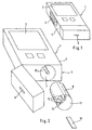
- Fig. 1 to 3 show in various views a compact handheld portable analyzer 1 for examining a medically significant component of a sample, in particular a biological fluid, such as blood, urine or saliva.
- a biological fluid such as blood, urine or saliva.
- This in Fig. 1 shown handheld analyzer 1 is used to determine the blood glucose content and has an integrated power source 2 in the form of commercial batteries or solar cells.
- the result of a study is displayed with a display device 3, preferably a power-saving liquid crystal display or an OLED display.
- the analysis handset 1 has a housing 4, which has a loading opening 5 for receiving a replaceable Drum magazine 6 in a magazine compartment 7, in which the drum magazine 6 by means of a drive stepwise about its geometric longitudinal axis is rotatable.
- Fig. 1 shows the analysis handset 1 with closed loading opening.
- 5 Fig. 2 and 3 show the analysis handset 1 with the loading opening 5.
- a part of the housing 4 is shown broken through, so that the magazine compartment 7 is visible.
- the housing 4 has an outlet opening 9 for analytical consumable 10 mounted in the drum magazine 6.
- These consumables 10 are preferably designed as test strips onto which a sample can be applied.
- a reagent contained in the test strip reacts with a medically significant component of the sample, so that the result of the reaction can be evaluated with an analysis device of the analysis hand-held device 1.
- Such an analysis device may for example contain an optical sensor as an analysis sensor, which detects a color change of a consumable 10 formed as a test strip, or contain a sensor which determines a change in conductivity of the sample.
- the drum magazine 6 has a plurality of annular chambers 12 arranged around its geometric longitudinal axis, which can contain analytical consumables 10.
- the chambers 12 can be successively positioned in a removal position, so that the consumables 10 can be removed as needed from the respective chamber 12 of the drum magazine 6 and output through the discharge opening 9 of the housing 4.
- the number of these chambers 12 can be chosen largely arbitrary. As a rule, 10 to 100 chambers 12 are expedient, preferably 15 to 30 chambers 12 are present.
- Each of the chambers 12 has on a front side of the drum magazine 6 a removal opening 13 for removing a consumable 10 and a discharge opening 13 opposite insertion opening 14 for insertion of a plunger 15 of a removal device 16.
- the insertion openings 14 and the Removal openings 13 are closed to protect the consumable 10 with a sealing film 17.
- the plunger 15 expendable 10 for use push out of the chambers 12, wherein the sealing film 17 of the insertion opening 14 from the plunger 15 and the sealing film 17 of the removal opening 13 is pierced by the consumable 10.
- a signal is generated which contains information as to whether one of the insertion openings 14 is sealed with sealing film 17 and thus a consumable 10 intended for use is contained therein.
- the drum testing device 18 it can be determined whether the drum magazine 6 is completely emptied.
- a counting device can also be provided which counts the number of consumables taken from the chambers 12 of a drum magazine 6 and outputs a "drum empty" signal when the maximum number is reached.
- Fig. 4 shows a schematic representation of a structure of the test unit 20, which detects a correct positioning of an analytical consumable 10 in the conveying path and additionally supports as a positioning correct positioning and preserves a correct positioning.
- the test unit 20 consists essentially of the control unit 40 and the optical sensor unit 30 and the electrical switching component 21. Both the optical sensor unit 30 and the electrical switching component 21 have the task of scanning a positioning of an analytical consumable 10 on the conveyor and a positioning Representing switching signal or a corresponding sensor signal to the control unit 40 to control based on a common evaluation of these signals, the analysis handset 1 or individual components thereof.
- the electrical switching component 21 has a displaceably formed pin 22 with an analytical consumable 10 associated end 23 which tapers in the direction of the consumable 10.
- the tapered end 23 of the pin 22 is formed so that it can engage in the measuring position of the consumable 10 in a recess 26 of the analytical consumable 10 and this can position 23 due to the conical shape of the end.
- a reliable optical analysis of the consumable 10 is ensured by means of the analysis sensor of the analyzer handset 1, which is also realized, for example, by the optical sensor unit 30.
- a reliable optical detection of a correct positioning of the consumable 10 by means of the optical sensor unit 30 can also be ensured.
- the recess 26 may also be formed as the consumable 10 penetrating hole; this is in Fig. 4 indicated by a dot-dashed line in the recess 26. Further advantageous embodiments of electrical switching components 21 are in the document EP 1 508 807 A2 described.
- the consumable 10 is not yet located in the measuring position in the conveying path in which the analysis is carried out. Consequently, the conically tapered end 23 of the pin 22 has not yet penetrated into the recess 26 or the hole in the consumable 10 and rests on the surface of the consumable 10.
- the consumable 10 was conveyed by the direction of the arrow in the conveying path to the position shown, in which its correct positioning in the conveying path by means of the test unit 20 is checked. In this review, it is checked whether a consumable 10 is in the test position in the conveying path, so it is so to speak, arrived from a chamber of the drum magazine by the conveying means of the removal device in this test position. After checking the correct positioning of the consumable 10 (in the dargestellellen test position), it is further promoted in the arrow direction until it reaches the measuring position in which the end 23 penetrates into the recess 26 and the analysis is performed.
- the consumable 10 is arranged in the conveying path in the region of the electrical switching component 21 or in the region of the optical sensor unit 30 lying on a support surface 29.
- the analytical consumable 10 of the pin 22 is moved from the rest position, which is determined by a contact of the end 23 on the support surface 29 up to the position shown in which it rests on the top of the consumable 10.
- This displacement is effected by the advance of the consumable 10 in the direction of the arrow and the sliding along the trailing edge of the tapered end 23.
- This displacement of the pin 22 perpendicular to the conveying path or to the bearing surface 29 takes place counter to a spring force which is generated by the spring 24.
- the spring 24 ensures that the pin 22 is held in the rest position until the consumable 10 moves it against the spring force in a shifted, for example in the position shown.
- an electrical contact 25 is closed or opened by means of the pin 22 and a mechanical contact 19 between the pin 22 and a contact spring 27.
- the two contacts of this electrical contact 25 are realized by the movable contact spring 27 and the fixed spring plate 28.
- the pin 22 allows in the situation shown a contact between the contact spring 27 and spring plate 28 for closing the electrical contact 25, whereby an electrical signal is generated, which indicates the correct positioning (the presence) of a consumable 10.
- the electrical contact 25 between contact spring 27 and spring plate 28 due to the mechanical contact 19, which presses the contact spring 27 down, thereby indicating that no consumable is present.
- the pin 22 is displaced by the spring 24 in the rest position, wherein it rests on the support surface 29 and thus no longer presses the contact spring 27 against the spring plate 28.
- the electrical contact 25 is opened and no electrical switching signal is transmitted to the control unit 40. This represents the switching information that no analytical consumable 10 is located in the monitored area of the electrical switching component 21.
- the electrical contact 25 is opened.
- the analysis handset 1 is regularly when it is not in use and is transported by the user. Especially when transported in bags or clothing, there is a risk that dirt particles penetrate through openings of the housing 4 of the analysis hand unit 1 and remain inside the housing 4. Dirt particles which come to rest in the region of the electrical contact 25 of the electrical switching component 21 and thereby prevent the electrical contacting of the contact spring 27 with the spring plate 28 are particularly harmful.
- the control unit 40 can not receive information about a correct positioning or the presence of the analytical consumable 10.
- the mechanical movement of the pin 22 or the mechanical contact 19 may be hindered by dirt particles.
- the electrical switching component 21 is embodied as an active optical sensor unit 30 and comprises an LED 31, which emits light of a limited frequency range in the direction of the consumable 10.
- the optical sensor unit 30 can be arranged on the side of the consumable 10, that of the consumer Side opposite, which faces the support surface 29.
- the optical sensor unit 30 were then arranged above the consumable means 10, ie on the same side as the electrical switching component 21, beside and immediately adjacent to this.
- the area of the support surface 29 facing the optical sensor unit 30 would then preferably be black in the area of the optical sensor unit 30. As a result, only a little light from the support surface 29 is scattered back.
- a consumable 10 which typically has a light, in particular white surface, for example, a white field used during the analysis for calibration purposes (so-called white value adjustment)
- the control unit 40 evaluates the two signals of the electrical switching component 21 and the optical sensor unit 30 together, whereby a check or verification of the electrical switching signal by means of the sensor signal.
- the optical sensor unit 30 is arranged on the side of the consumable 10 which faces the support surface 29.
- the optical sensor unit 30 is thus arranged below the consumable means 10, ie on the side of the consumable means 10 which is opposite the electrical switching component 21.
- the support surface 29 has an opening or a transparent window region 33 in the region of the optical sensor unit 30. If there is no consumable in the area irradiated by the optical sensor unit 30, only little stray light will be present scattered back to the photosensor 32.
- a consumable 10 which typically has a light, in particular white surface, for example, a white field used in the analysis for calibration purposes (so-called white value adjustment)
- the amount of reflected light increases considerably.
- the reflected light is detected by a photosensor 32 of the optical sensor unit 30.
- These two states differ significantly in the amount of light reflected and received by the photosensor 32, so that these two states can be distinguished very securely by means of the optical sensor unit 30.
- the latter emits to the control unit 40 a corresponding sensor signal which either represents the state of correct positioning of the consumable 10 in the conveying path and thus on the bearing surface 29 or represents the condition of non-existing consumable 10 in the conveying path.
- the control unit 40 evaluates the two signals of the electrical switching component 21 and the optical sensor unit 30 together, whereby a check or verification of the electrical switching signal by means of the sensor signal.
- the analysis can be carried out with an analysis sensor directly in this position of the consumable 10. If, however, the optical sensor unit 30 simultaneously serves as an analysis sensor or the analysis sensor is integrated into the optical sensor unit 30, it is generally necessary to convey the consumable 10 from the position shown in the direction of the arrow into the measuring position until, for example, a photometrically measured test field in the measuring position Visual range of the analysis sensor is located. In the measuring position of the consumable 10 then the end 23 of the pin 22 can penetrate into the recess 26.
- either the electrical contact 25 remain closed and thus continue to signal the correct positioning, ie the presence of a consumable 10.
- the electrical contact 25 opens in the measuring position of the consumable 10, thereby obtaining a signal indicating that the consumable 10 has reached the measuring position.
- the fact that the opened electrical contact 25 then apparently indicates that no consumable 10 is present can be taken into account by means of a corresponding casserole control by means of the control unit 40, in which the correct positioning of the consumable 10 in the measuring position has previously been verified.
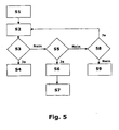
- Fig. 5 is schematically illustrated in the form of a flowchart example, the review or the control of the analysis handset with a special attention to the function of the test unit 20.
- a strip-shaped consumable 10 is removed from the drum magazine 6 in step S2 by means of the removal device 16 and placed on the conveying path and placed on the conveyance path Promoted direction of the analysis sensor.
- the strip-shaped consumable 10 reaches the range of the electrical switching component 21 and the optical sensor unit 30.
- the strip-shaped consumable 10 of the pin 22 of the electrical switching component 21 is moved, thereby closing the electrical contact between the spring plate 28 and the contact spring 27.
- This is the switching signal which represents the state of correct positioning of the consumable 10, delivered to the control unit 40. This detection takes place in step S3.
- the analysis sensor is activated in step S4 and the examination of the sample to be analyzed on a medically important component, such as glucose, is performed.
- the measurement result is subsequently output by means of the display device 3.
- step S3 If, in accordance with step S3, the state of no correct positioning of the consumable 10 is detected by the electrical switching component 21 and forwarded to the control unit 40, an optical detection of the correct positioning by means of the optical sensor unit 30 is undertaken below. This is done in step S5.
- the optical sensor unit 30 is activated exclusively in this case, otherwise it is deactivated.
- the optical sensor unit 30 is thus activated only to verify or verify the switching signal of the electrical switching component 21 when the switching signal of the electrical switching component 21 indicates that there is no analytical consumable 10 in the correct position on the conveyor. As a result, a very energy-saving operation of the analysis hand-held device 1 is made possible.
- the optical sensor unit 30 is automatically activated to verify or verify the switching signal of the electrical switching component 21 when the extraction device 16 has been activated to convey an analytical consumable 10 to the conveying path, but the switching signal of the electrical switching component 21 indicates that it is not analytical Consumables 10 in the correct position on the conveyor.
- step S5 If it is determined in step S5 that no consumable 10 is present in the detection range of the optical sensor unit 30, this corresponds to confirmation of the electrical switching signal, whereupon the control unit 40 activates the extraction device 16 to supply the next consumable 10 from the next chamber of the drum magazine 6 and convey towards the analysis sensor. This ensures that, according to the requirement according to step S1, a consumable 10 is conveyed in order to carry out the desired analysis. If it is determined by the drum testing device 18 or a counting device according to step S8 that the drum is completely emptied and thus no more consumable 10 is contained in the drum magazine 6, this is done to the user by means of the display device 3 notified according to step S9 and set the further operation of the analysis handset 1.
- step S5 If a correct positioning and thus the presence of the consumable means 10 is determined by the optical sensor unit 30 in accordance with step S5 and a corresponding sensor signal is output to the control unit 40, then the contradictory signal content is detected by the control unit 40 and interpreted as a malfunction of the analyzer handset 1.
- This malfunction is characterized in that a strip-shaped consumable 10 is present in the region of the electrical switching component 21 and in the region of the optical sensor 30, but this is not detected by the electrical switching component 21 and thereby the measuring process according to step S4 is not started.
- an error message is output by means of the display device 3 in accordance with step S6, which indicates this malfunction and prompts the user to carry out a cleaning of the electrical contacts 27, 28 of the switching component 21. This can be done automatically by starting a corresponding cleaning program of the analyzer handset 1. As a result, the functionality of the electrical switching component 21 is restored and thus the functionality of the analysis handset 1 recovered.
- the consumable 10 is ejected from the device according to step S7 and thus created the possibility to carry out a successful analysis in the future after cleaning.
- step S5 an evaluation of the switching signal of the electrical switching component 21 and of the sensor signal of the optical sensor unit 30 thus takes place overall, and depending on the comparison of these signals, the analysis handset 1 is controlled by means of the control unit 40.
- the described operating sequence ensures that the malfunctions of the so-called continuous strip slide, in which consumables 10 are continuously conveyed out of the drum magazine 6 with the aid of the removal device 16, without causing any analysis comes, or the malfunction of StMOklemmers, in which a further consumable 10 is pushed onto a supply means present in the conveying path, which leads to a wedging of the consumable means 10 in the conveying path is largely prevented.
Claims (16)
- Appareil d'analyse portable (1) pour tester un échantillon, en particulier un liquide biologique, à l'égard d'un composant médicalement significatif, comprenant
un dispositif d'affichage (3),
un boîtier (4),
une ouverture de chargement (5) destinée à recevoir un magasin échangeable (6), en particulier un magasin à tambour pouvant contenir des consommables analytiques (10), notamment des bandelettes de test,
un dispositif de prélèvement (16) destiné à prélever un consommable analytique (10) dans le magasin (6) et à l'envoyer sur un parcours de transport,
un capteur d'analyse vers lequel un consommable analytique (10) peut être acheminé sur le parcours de transport, et
une unité de contrôle (20) qui constate un positionnement correct d'un consommable analytique (10) dans le parcours de transport,
caractérisé en ce que
l'unité de contrôle (20) comprend
un composant de commutation électrique (21), qui explore mécaniquement un positionnement d'un consommable analytique (10) sur le parcours de transport, qui prend au moins une position de commutation représentant la présence d'un consommable analytique (10) et qui délivre un signal de commutation en fonction du positionnement du consommable analytique (10),
ainsi qu'un module capteur optique (30), qui explore optiquement un positionnement d'un consommable analytique (10) sur le parcours de transport et qui délivre un signal capteur en fonction du positionnement du consommable analytique (10),
et une unité de commande (40), qui exploite le signal de commutation du composant de commutation électrique (21) et le signal capteur du module capteur optique (30) et commande l'appareil d'analyse portable (1) en fonction de la comparaison de ces signaux. - Appareil d'analyse portable (1) selon la revendication 1, caractérisé en ce que le composant de commutation électrique (21) comprend un doigt (22) monté coulissant, en particulier sur ressort, comme élément de commutation, avec une extrémité conique (23) tournée vers le consommable analytique (10), et le consommable analytique (10) présente comme conformation de surface spécifique à la position au moins une saillie et/ou un creux (26) correspondant à l'extrémité conique du doigt (22).
- Appareil d'analyse portable (1) selon la revendication 2, caractérisé en ce que la conformation de surface spécifique à la position présente un contour qui influence la déflexion du doigt (22) conçu comme élément de commutation selon la position du consommable analytique (10) dans le parcours de transport, en particulier une rainure variable en largeur et/ou profondeur ou une rampe variable en largeur et/ou hauteur.
- Appareil d'analyse portable (1) selon l'une des revendications précédentes, caractérisé en ce que le module capteur optique (30) est conçu pour déterminer la position d'un élément de commutation du composant de commutation électrique (21), en particulier d'un doigt coulissant (22).
- Appareil d'analyse portable (1) selon l'une des revendications 1 à 3, caractérisé en ce que le module capteur optique (30) destiné à déterminer la présence et/ou la position du consommable analytique (10) est conçu à l'aide des propriétés optiques réfléchissantes ou transmettrices de ce dernier.
- Appareil d'analyse portable (1) selon l'une des revendications précédentes, caractérisé en ce que le module capteur optique (30) forme un module capteur commun avec le capteur d'analyse.
- Appareil d'analyse portable (1) selon l'une des revendications précédentes, caractérisé en ce que le prélèvement d'un consommable analytique (10) dans le magasin (6) par le dispositif de prélèvement (16) est empêché par l'unité de commande (40) lorsque soit le signal de commutation du composant de commutation électrique (21), soit le signal capteur du module capteur optique (30) représente un positionnement correct et l'autre signal respectif un positionnement non correct d'un consommable analytique (10), dans le parcours de transport et en ce que de préférence un message d'erreur s'affiche en plus sur le dispositif d'affichage (3).
- Appareil d'analyse portable (1) selon l'une des revendications précédentes, caractérisé en ce que le capteur d'analyse (15) destiné à tester un échantillon à l'égard d'un composant médicalement significatif est activable lorsque, au moyen d'un signal de commutation du composant de commutation électrique (21) représentant un positionnement correct d'un consommable analytique (10), un positionnement correct d'un consommable analytique (10) dans le parcours de transport a été constaté.
- Appareil d'analyse portable (1) selon l'une des revendications précédentes, caractérisé en ce que le module capteur optique (30) n'est activable pour contrôler, respectivement vérifier le signal de commutation du composant de commutation électrique (21) que lorsque le signal de commutation du composant de commutation électrique (21) indique qu'aucun consommable analytique (10) n'est en position correcte sur le parcours de transport.
- Procédé permettant de faire fonctionner un appareil d'analyse portable (1) pour tester un échantillon, en particulier un liquide biologique, à l'égard d'un composant médicalement significatif, l'appareil d'analyse portable (1) comprenant un dispositif d'affichage (3),
un dispositif de prélèvement (16) destiné à prélever un consommable analytique (10) dans un magasin, en particulier un magasin à tambour (6), et à l'envoyer sur un parcours de transport,
un capteur d'analyse vers lequel un consommable analytique (10) peut être acheminé sur le parcours de transport, et
une unité de contrôle (20) qui constate un positionnement correct d'un consommable analytique (10) dans le parcours de transport,
caractérisé en ce que
après une activation de l'appareil d'analyse portable (1)
et le prélèvement subséquent d'un consommable analytique (10) dans le magasin (6) et son envoi sur le parcours de transport,
des signaux d'un composant de commutation électrique (21), lequel explore mécaniquement un positionnement d'un consommable analytique (10) sur le parcours de transport, et d'un module capteur optique (30), lequel explore optiquement un positionnement d'un consommable analytique (10) sur le parcours de transport, sont évalués au moyen d'une unité de commande (40) et l'appareil d'analyse portable (1) est commandé en fonction de la comparaison de ces signaux. - Procédé permettant de faire fonctionner un appareil d'analyse portable (1) selon la revendication 10, caractérisé en ce que le processus de mesure par le capteur d'analyse destiné à tester un échantillon à l'égard d'un composant médicalement significatif est autorisé lorsqu'un positionnement correct a été signalé par le composant de commutation électrique (21).
- Procédé permettant de faire fonctionner un appareil d'analyse portable (1) selon l'une des revendications 10 à 11, caractérisé en ce que le module capteur optique (30) est activé automatiquement pour contrôler, respectivement vérifier le signal de commutation du composant de commutation électrique (21) lorsque le signal de commutation du composant de commutation électrique (21) indique qu'aucun consommable analytique (10) n'est en position correcte sur le parcours de transport.
- Procédé permettant de faire fonctionner un appareil d'analyse portable (1) selon l'une des revendications 10 à 12, caractérisé en ce que le module capteur optique (30) est activé automatiquement pour contrôler, respectivement vérifier le signal de commutation du composant de commutation électrique (21) lorsque le dispositif de prélèvement (16) destiné à amener un consommable analytique (10) sur le parcours de transport a été activé mais que le signal de commutation du composant de commutation électrique (21) indique qu'aucun consommable analytique (10) n'est en position correcte sur le parcours de transport.
- Procédé permettant de faire fonctionner un appareil d'analyse portable (1) selon l'une des revendications 10 à 13, caractérisé en ce que le prélèvement d'un consommable analytique (10) par le dispositif de prélèvement (16) est empêché lorsque soit le signal du composant de commutation électrique (21), soit celui du module capteur optique (30) représente un positionnement correct et l'autre signal respectif un positionnement non correct d'un consommable analytique (10), et en ce que de préférence un message d'erreur s'affiche en plus sur le dispositif d'affichage (3).
- Procédé permettant de faire fonctionner un appareil d'analyse portable (1) selon l'une des revendications 10 à 14, caractérisé en ce que le dispositif de prélèvement (16) est activé lorsque le composant de commutation électrique (21) constate un positionnement non correct d'un consommable analytique (10) et que le positionnement non correct est confirmé par le module capteur optique (30).
- Procédé permettant de faire fonctionner un appareil d'analyse portable (1) selon la revendication 15, caractérisé en ce qu'une nouvelle activation du dispositif de prélèvement (16) est empêchée et de préférence un message d'erreur est affiché lorsqu'il est constaté que le magasin (6) est totalement vide.
Priority Applications (8)
| Application Number | Priority Date | Filing Date | Title |
|---|---|---|---|
| PL07010017T PL1995594T3 (pl) | 2007-05-19 | 2007-05-19 | Ręczny przyrząd analityczny do badania próbki |
| ES07010017T ES2326496T3 (es) | 2007-05-19 | 2007-05-19 | Aparato analizador portatil para examinar una muestra. |
| EP07010017A EP1995594B1 (fr) | 2007-05-19 | 2007-05-19 | Appareil d'analyse portable pour tester des échantillons |
| AT07010017T ATE436014T1 (de) | 2007-05-19 | 2007-05-19 | Analysehandgerät zum untersuchen einer probe |
| DE502007001040T DE502007001040D1 (de) | 2007-05-19 | 2007-05-19 | Analysehandgerät zum Untersuchen einer Probe |
| CA2630719A CA2630719C (fr) | 2007-05-19 | 2008-05-07 | Analyseur a main pour essai d'echantillon |
| JP2008124594A JP4604109B2 (ja) | 2007-05-19 | 2008-05-12 | 試料検査のための手持ち式分析装置 |
| CNA2008100990773A CN101308133A (zh) | 2007-05-19 | 2008-05-16 | 用于测试样本的手持式分析器 |
Applications Claiming Priority (1)
| Application Number | Priority Date | Filing Date | Title |
|---|---|---|---|
| EP07010017A EP1995594B1 (fr) | 2007-05-19 | 2007-05-19 | Appareil d'analyse portable pour tester des échantillons |
Publications (2)
| Publication Number | Publication Date |
|---|---|
| EP1995594A1 EP1995594A1 (fr) | 2008-11-26 |
| EP1995594B1 true EP1995594B1 (fr) | 2009-07-08 |
Family
ID=38669973
Family Applications (1)
| Application Number | Title | Priority Date | Filing Date |
|---|---|---|---|
| EP07010017A Active EP1995594B1 (fr) | 2007-05-19 | 2007-05-19 | Appareil d'analyse portable pour tester des échantillons |
Country Status (8)
| Country | Link |
|---|---|
| EP (1) | EP1995594B1 (fr) |
| JP (1) | JP4604109B2 (fr) |
| CN (1) | CN101308133A (fr) |
| AT (1) | ATE436014T1 (fr) |
| CA (1) | CA2630719C (fr) |
| DE (1) | DE502007001040D1 (fr) |
| ES (1) | ES2326496T3 (fr) |
| PL (1) | PL1995594T3 (fr) |
Cited By (1)
| Publication number | Priority date | Publication date | Assignee | Title |
|---|---|---|---|---|
| US8394637B2 (en) | 2008-06-02 | 2013-03-12 | Roche Diagnostics Operations, Inc. | Handheld analyzer for testing a sample |
Families Citing this family (5)
| Publication number | Priority date | Publication date | Assignee | Title |
|---|---|---|---|---|
| JP2013545109A (ja) * | 2010-12-09 | 2013-12-19 | ケヴァル,アルテュール | 流体サンプル分析用のマイクロ流体デバイス |
| CN103837474A (zh) * | 2012-11-20 | 2014-06-04 | 永龄生技股份有限公司 | 试纸盘读取器及诊断装置 |
| CN108814621B (zh) * | 2018-04-11 | 2021-09-07 | 于雪 | 一种防护式传染病血样采集装置 |
| CN109567827B (zh) * | 2018-11-20 | 2019-12-13 | 陈欣 | 一种检验科智能指血检查装置 |
| CN114551140B (zh) * | 2020-11-25 | 2023-12-29 | 广州好芝生物科技有限公司 | 开关组件、检测装置及基于开关组件的控制方法 |
Family Cites Families (12)
| Publication number | Priority date | Publication date | Assignee | Title |
|---|---|---|---|---|
| JPS61165679A (ja) * | 1985-01-18 | 1986-07-26 | Matsushita Electric Ind Co Ltd | 光学式紙検出装置 |
| JPS61278781A (ja) * | 1985-06-04 | 1986-12-09 | Fuji Xerox Co Ltd | センサ装置 |
| JP2812625B2 (ja) * | 1992-10-19 | 1998-10-22 | 株式会社日立製作所 | 液体試料自動分析装置 |
| US6335203B1 (en) * | 1994-09-08 | 2002-01-01 | Lifescan, Inc. | Optically readable strip for analyte detection having on-strip orientation index |
| DK0901634T3 (da) * | 1996-05-30 | 2002-06-10 | Radiometer Medical As | System til bestemmelse af mindst en parameter i mindst en prøve af en fysiologisk væske samt en kassette |
| DE69626016T2 (de) * | 1996-09-27 | 2004-01-08 | Inverness Medical Switzerland Gmbh | Test-Kit und Vorrichtungen |
| DE19844500A1 (de) * | 1998-09-29 | 2000-03-30 | Roche Diagnostics Gmbh | Verfahren zur photometrischen Auswertung von Testelementen |
| EP1031470A1 (fr) * | 1999-02-25 | 2000-08-30 | Siemens Aktiengesellschaft | Dispositif pour la protection des passagers dans un véhicule |
| JP2006511820A (ja) * | 2002-12-23 | 2006-04-06 | エフ ホフマン−ラ ロッシュ アクチェン ゲゼルシャフト | 分析システム内の試験エレメントを搬送するための移送装置 |
| DE10338446A1 (de) * | 2003-08-21 | 2005-03-31 | Roche Diagnostics Gmbh | Positioniereinrichtung für ein Testelement |
| DE10361261B4 (de) * | 2003-12-24 | 2006-02-09 | Roche Diagnostics Gmbh | Analysehandgerät |
| DE102004010529B4 (de) * | 2004-03-04 | 2007-09-06 | Roche Diagnostics Gmbh | Analysehandgerät |
-
2007
- 2007-05-19 PL PL07010017T patent/PL1995594T3/pl unknown
- 2007-05-19 AT AT07010017T patent/ATE436014T1/de active
- 2007-05-19 DE DE502007001040T patent/DE502007001040D1/de active Active
- 2007-05-19 ES ES07010017T patent/ES2326496T3/es active Active
- 2007-05-19 EP EP07010017A patent/EP1995594B1/fr active Active
-
2008
- 2008-05-07 CA CA2630719A patent/CA2630719C/fr not_active Expired - Fee Related
- 2008-05-12 JP JP2008124594A patent/JP4604109B2/ja not_active Expired - Fee Related
- 2008-05-16 CN CNA2008100990773A patent/CN101308133A/zh active Pending
Cited By (1)
| Publication number | Priority date | Publication date | Assignee | Title |
|---|---|---|---|---|
| US8394637B2 (en) | 2008-06-02 | 2013-03-12 | Roche Diagnostics Operations, Inc. | Handheld analyzer for testing a sample |
Also Published As
| Publication number | Publication date |
|---|---|
| ATE436014T1 (de) | 2009-07-15 |
| JP2008292479A (ja) | 2008-12-04 |
| ES2326496T3 (es) | 2009-10-13 |
| EP1995594A1 (fr) | 2008-11-26 |
| CA2630719A1 (fr) | 2008-11-19 |
| JP4604109B2 (ja) | 2010-12-22 |
| DE502007001040D1 (de) | 2009-08-20 |
| CN101308133A (zh) | 2008-11-19 |
| CA2630719C (fr) | 2011-04-12 |
| PL1995594T3 (pl) | 2009-12-31 |
Similar Documents
| Publication | Publication Date | Title |
|---|---|---|
| EP1697048B1 (fr) | Appareil manuel d'analyse | |
| EP1879018B1 (fr) | Système d'analyse et procédé destinés à l'analyse d'un échantillon sur un élément de test analytique | |
| EP1995594B1 (fr) | Appareil d'analyse portable pour tester des échantillons | |
| EP0922959B1 (fr) | Système d'analyse des échantillons liquides | |
| EP1825257B1 (fr) | Systeme de diagnostic destine a la determination de concentrations de substances dans des echantillons liquides | |
| EP1789192B1 (fr) | Element de test analytique | |
| EP2830763B1 (fr) | Système de cartouche à puce jetable intégré pour analyses multi-paramètres mobiles de substances chimiques et/ou biologiques | |
| DE1673340C3 (fr) | ||
| DE10360786B4 (de) | Analysehandgerät | |
| EP2139396B1 (fr) | Appareil de perçage et appareil d'analyse | |
| EP1213579B1 (fr) | Appareil pour l'analyse d'échantillons liquides comprenant une unité de contrôle de position | |
| EP1745284B1 (fr) | Appareil d'analyse a main comportant une section de transport pour des elements d'analyse | |
| DE112010000810T5 (de) | Vorrichtung zur Vorbehandlung von biologischen Proben und mit dieser ausgestattetes Massenspektrometer | |
| EP1716418A2 (fr) | Dispositif et procede d'analyse optique de bandelettes de test | |
| AT504919B1 (de) | Durchlichtmessvorrichtung | |
| EP1921441B1 (fr) | Appareil d'analyse d'un élément de test d'échantillon et système d'analyse | |
| EP1507589B1 (fr) | Dispositif de prelevement d'echantillons liquides | |
| DE3217591A1 (de) | Analysengeraet, insbesondere zur untersuchung von fluessigkeitsproben | |
| EP0255077B1 (fr) | Dispositif permettant de détecter la position de la zone test d'une bande test et de tourner celle-ci | |
| EP1579223A2 (fr) | Dispositif de transport servant a transporter des elements de test dans un systeme d'analyse | |
| EP0990908A1 (fr) | Analyseur automatisé avec moyens de controle des procédures de pipettage | |
| EP1621885A2 (fr) | Système d'analyse avec un support pour des élements analytiques | |
| EP1508807B1 (fr) | Unité de positionnement d'éléments de test | |
| EP3418749B1 (fr) | Surveillance optique de processus de mélange | |
| WO2022263469A1 (fr) | Appareil et procédé de lecture d'élément d'échantillon |
Legal Events
| Date | Code | Title | Description |
|---|---|---|---|
| PUAI | Public reference made under article 153(3) epc to a published international application that has entered the european phase |
Free format text: ORIGINAL CODE: 0009012 |
|
| 17P | Request for examination filed |
Effective date: 20080116 |
|
| AK | Designated contracting states |
Kind code of ref document: A1 Designated state(s): AT BE BG CH CY CZ DE DK EE ES FI FR GB GR HU IE IS IT LI LT LU LV MC MT NL PL PT RO SE SI SK TR |
|
| AX | Request for extension of the european patent |
Extension state: AL BA HR MK RS |
|
| GRAP | Despatch of communication of intention to grant a patent |
Free format text: ORIGINAL CODE: EPIDOSNIGR1 |
|
| GRAS | Grant fee paid |
Free format text: ORIGINAL CODE: EPIDOSNIGR3 |
|
| GRAA | (expected) grant |
Free format text: ORIGINAL CODE: 0009210 |
|
| AK | Designated contracting states |
Kind code of ref document: B1 Designated state(s): AT BE BG CH CY CZ DE DK EE ES FI FR GB GR HU IE IS IT LI LT LU LV MC MT NL PL PT RO SE SI SK TR |
|
| REG | Reference to a national code |
Ref country code: GB Ref legal event code: FG4D Free format text: NOT ENGLISH |
|
| REG | Reference to a national code |
Ref country code: CH Ref legal event code: EP |
|
| AKX | Designation fees paid |
Designated state(s): AT BE BG CH CY CZ DE DK EE ES FI FR GB GR HU IE IS IT LI LT LU LV MC MT NL PL PT RO SE SI SK TR |
|
| REG | Reference to a national code |
Ref country code: IE Ref legal event code: FG4D |
|
| REF | Corresponds to: |
Ref document number: 502007001040 Country of ref document: DE Date of ref document: 20090820 Kind code of ref document: P |
|
| REG | Reference to a national code |
Ref country code: ES Ref legal event code: FG2A Ref document number: 2326496 Country of ref document: ES Kind code of ref document: T3 |
|
| PG25 | Lapsed in a contracting state [announced via postgrant information from national office to epo] |
Ref country code: SI Free format text: LAPSE BECAUSE OF FAILURE TO SUBMIT A TRANSLATION OF THE DESCRIPTION OR TO PAY THE FEE WITHIN THE PRESCRIBED TIME-LIMIT Effective date: 20090708 |
|
| REG | Reference to a national code |
Ref country code: PL Ref legal event code: T3 |
|
| PG25 | Lapsed in a contracting state [announced via postgrant information from national office to epo] |
Ref country code: FI Free format text: LAPSE BECAUSE OF FAILURE TO SUBMIT A TRANSLATION OF THE DESCRIPTION OR TO PAY THE FEE WITHIN THE PRESCRIBED TIME-LIMIT Effective date: 20090708 Ref country code: LT Free format text: LAPSE BECAUSE OF FAILURE TO SUBMIT A TRANSLATION OF THE DESCRIPTION OR TO PAY THE FEE WITHIN THE PRESCRIBED TIME-LIMIT Effective date: 20090708 Ref country code: IS Free format text: LAPSE BECAUSE OF FAILURE TO SUBMIT A TRANSLATION OF THE DESCRIPTION OR TO PAY THE FEE WITHIN THE PRESCRIBED TIME-LIMIT Effective date: 20091108 |
|
| REG | Reference to a national code |
Ref country code: IE Ref legal event code: FD4D |
|
| PG25 | Lapsed in a contracting state [announced via postgrant information from national office to epo] |
Ref country code: LV Free format text: LAPSE BECAUSE OF FAILURE TO SUBMIT A TRANSLATION OF THE DESCRIPTION OR TO PAY THE FEE WITHIN THE PRESCRIBED TIME-LIMIT Effective date: 20090708 |
|
| PG25 | Lapsed in a contracting state [announced via postgrant information from national office to epo] |
Ref country code: PT Free format text: LAPSE BECAUSE OF FAILURE TO SUBMIT A TRANSLATION OF THE DESCRIPTION OR TO PAY THE FEE WITHIN THE PRESCRIBED TIME-LIMIT Effective date: 20091109 Ref country code: BG Free format text: LAPSE BECAUSE OF FAILURE TO SUBMIT A TRANSLATION OF THE DESCRIPTION OR TO PAY THE FEE WITHIN THE PRESCRIBED TIME-LIMIT Effective date: 20091008 |
|
| PG25 | Lapsed in a contracting state [announced via postgrant information from national office to epo] |
Ref country code: EE Free format text: LAPSE BECAUSE OF FAILURE TO SUBMIT A TRANSLATION OF THE DESCRIPTION OR TO PAY THE FEE WITHIN THE PRESCRIBED TIME-LIMIT Effective date: 20090708 Ref country code: DK Free format text: LAPSE BECAUSE OF FAILURE TO SUBMIT A TRANSLATION OF THE DESCRIPTION OR TO PAY THE FEE WITHIN THE PRESCRIBED TIME-LIMIT Effective date: 20090708 Ref country code: CZ Free format text: LAPSE BECAUSE OF FAILURE TO SUBMIT A TRANSLATION OF THE DESCRIPTION OR TO PAY THE FEE WITHIN THE PRESCRIBED TIME-LIMIT Effective date: 20090708 Ref country code: IE Free format text: LAPSE BECAUSE OF FAILURE TO SUBMIT A TRANSLATION OF THE DESCRIPTION OR TO PAY THE FEE WITHIN THE PRESCRIBED TIME-LIMIT Effective date: 20090708 Ref country code: RO Free format text: LAPSE BECAUSE OF FAILURE TO SUBMIT A TRANSLATION OF THE DESCRIPTION OR TO PAY THE FEE WITHIN THE PRESCRIBED TIME-LIMIT Effective date: 20090708 |
|
| PLBE | No opposition filed within time limit |
Free format text: ORIGINAL CODE: 0009261 |
|
| STAA | Information on the status of an ep patent application or granted ep patent |
Free format text: STATUS: NO OPPOSITION FILED WITHIN TIME LIMIT |
|
| PG25 | Lapsed in a contracting state [announced via postgrant information from national office to epo] |
Ref country code: SK Free format text: LAPSE BECAUSE OF FAILURE TO SUBMIT A TRANSLATION OF THE DESCRIPTION OR TO PAY THE FEE WITHIN THE PRESCRIBED TIME-LIMIT Effective date: 20090708 |
|
| 26N | No opposition filed |
Effective date: 20100409 |
|
| PG25 | Lapsed in a contracting state [announced via postgrant information from national office to epo] |
Ref country code: GR Free format text: LAPSE BECAUSE OF FAILURE TO SUBMIT A TRANSLATION OF THE DESCRIPTION OR TO PAY THE FEE WITHIN THE PRESCRIBED TIME-LIMIT Effective date: 20091009 |
|
| BERE | Be: lapsed |
Owner name: F. HOFFMANN-LA ROCHE A.G. Effective date: 20100531 Owner name: ROCHE DIAGNOSTICS G.M.B.H. Effective date: 20100531 |
|
| PG25 | Lapsed in a contracting state [announced via postgrant information from national office to epo] |
Ref country code: MC Free format text: LAPSE BECAUSE OF NON-PAYMENT OF DUE FEES Effective date: 20100531 |
|
| PG25 | Lapsed in a contracting state [announced via postgrant information from national office to epo] |
Ref country code: IT Free format text: LAPSE BECAUSE OF NON-PAYMENT OF DUE FEES Effective date: 20100519 Ref country code: BE Free format text: LAPSE BECAUSE OF NON-PAYMENT OF DUE FEES Effective date: 20100531 |
|
| PG25 | Lapsed in a contracting state [announced via postgrant information from national office to epo] |
Ref country code: MT Free format text: LAPSE BECAUSE OF FAILURE TO SUBMIT A TRANSLATION OF THE DESCRIPTION OR TO PAY THE FEE WITHIN THE PRESCRIBED TIME-LIMIT Effective date: 20090708 |
|
| PGFP | Annual fee paid to national office [announced via postgrant information from national office to epo] |
Ref country code: FR Payment date: 20110511 Year of fee payment: 5 Ref country code: ES Payment date: 20110519 Year of fee payment: 5 |
|
| PGFP | Annual fee paid to national office [announced via postgrant information from national office to epo] |
Ref country code: GB Payment date: 20110421 Year of fee payment: 5 Ref country code: PL Payment date: 20110316 Year of fee payment: 5 Ref country code: NL Payment date: 20110523 Year of fee payment: 5 |
|
| PGFP | Annual fee paid to national office [announced via postgrant information from national office to epo] |
Ref country code: IT Payment date: 20110523 Year of fee payment: 5 |
|
| REG | Reference to a national code |
Ref country code: CH Ref legal event code: PL |
|
| PG25 | Lapsed in a contracting state [announced via postgrant information from national office to epo] |
Ref country code: LI Free format text: LAPSE BECAUSE OF NON-PAYMENT OF DUE FEES Effective date: 20110531 Ref country code: CH Free format text: LAPSE BECAUSE OF NON-PAYMENT OF DUE FEES Effective date: 20110531 |
|
| PG25 | Lapsed in a contracting state [announced via postgrant information from national office to epo] |
Ref country code: CY Free format text: LAPSE BECAUSE OF FAILURE TO SUBMIT A TRANSLATION OF THE DESCRIPTION OR TO PAY THE FEE WITHIN THE PRESCRIBED TIME-LIMIT Effective date: 20090708 |
|
| PG25 | Lapsed in a contracting state [announced via postgrant information from national office to epo] |
Ref country code: SE Free format text: LAPSE BECAUSE OF FAILURE TO SUBMIT A TRANSLATION OF THE DESCRIPTION OR TO PAY THE FEE WITHIN THE PRESCRIBED TIME-LIMIT Effective date: 20090708 Ref country code: LU Free format text: LAPSE BECAUSE OF NON-PAYMENT OF DUE FEES Effective date: 20100519 Ref country code: HU Free format text: LAPSE BECAUSE OF FAILURE TO SUBMIT A TRANSLATION OF THE DESCRIPTION OR TO PAY THE FEE WITHIN THE PRESCRIBED TIME-LIMIT Effective date: 20100109 |
|
| PG25 | Lapsed in a contracting state [announced via postgrant information from national office to epo] |
Ref country code: TR Free format text: LAPSE BECAUSE OF FAILURE TO SUBMIT A TRANSLATION OF THE DESCRIPTION OR TO PAY THE FEE WITHIN THE PRESCRIBED TIME-LIMIT Effective date: 20090708 |
|
| REG | Reference to a national code |
Ref country code: NL Ref legal event code: V1 Effective date: 20121201 |
|
| GBPC | Gb: european patent ceased through non-payment of renewal fee |
Effective date: 20120519 |
|
| PG25 | Lapsed in a contracting state [announced via postgrant information from national office to epo] |
Ref country code: IT Free format text: LAPSE BECAUSE OF NON-PAYMENT OF DUE FEES Effective date: 20120519 |
|
| REG | Reference to a national code |
Ref country code: FR Ref legal event code: ST Effective date: 20130131 |
|
| PG25 | Lapsed in a contracting state [announced via postgrant information from national office to epo] |
Ref country code: NL Free format text: LAPSE BECAUSE OF NON-PAYMENT OF DUE FEES Effective date: 20121201 |
|
| PG25 | Lapsed in a contracting state [announced via postgrant information from national office to epo] |
Ref country code: FR Free format text: LAPSE BECAUSE OF NON-PAYMENT OF DUE FEES Effective date: 20120531 Ref country code: GB Free format text: LAPSE BECAUSE OF NON-PAYMENT OF DUE FEES Effective date: 20120519 |
|
| REG | Reference to a national code |
Ref country code: AT Ref legal event code: MM01 Ref document number: 436014 Country of ref document: AT Kind code of ref document: T Effective date: 20120519 |
|
| PG25 | Lapsed in a contracting state [announced via postgrant information from national office to epo] |
Ref country code: AT Free format text: LAPSE BECAUSE OF NON-PAYMENT OF DUE FEES Effective date: 20120519 |
|
| REG | Reference to a national code |
Ref country code: ES Ref legal event code: FD2A Effective date: 20130820 |
|
| PG25 | Lapsed in a contracting state [announced via postgrant information from national office to epo] |
Ref country code: PL Free format text: LAPSE BECAUSE OF NON-PAYMENT OF DUE FEES Effective date: 20120519 |
|
| REG | Reference to a national code |
Ref country code: PL Ref legal event code: LAPE |
|
| PG25 | Lapsed in a contracting state [announced via postgrant information from national office to epo] |
Ref country code: ES Free format text: LAPSE BECAUSE OF NON-PAYMENT OF DUE FEES Effective date: 20120520 |
|
| REG | Reference to a national code |
Ref country code: DE Ref legal event code: R081 Ref document number: 502007001040 Country of ref document: DE Owner name: ROCHE DIABETES CARE GMBH, DE Free format text: FORMER OWNER: ROCHE DIAGNOSTICS GMBH, 68305 MANNHEIM, DE |
|
| PGFP | Annual fee paid to national office [announced via postgrant information from national office to epo] |
Ref country code: DE Payment date: 20230412 Year of fee payment: 17 |